Error amplification apparatus and driving circuit including the same
a technology of amplification apparatus and a driving circuit, applied in the direction of electric variable regulation, process and machine control, instruments, etc., can solve the problems of compensation capacitors with such capacitances that cannot be integrated into integrated circuits, output current,
- Summary
- Abstract
- Description
- Claims
- Application Information
AI Technical Summary
Benefits of technology
Problems solved by technology
Method used
Image

Examples
first embodiment
A First Embodiment
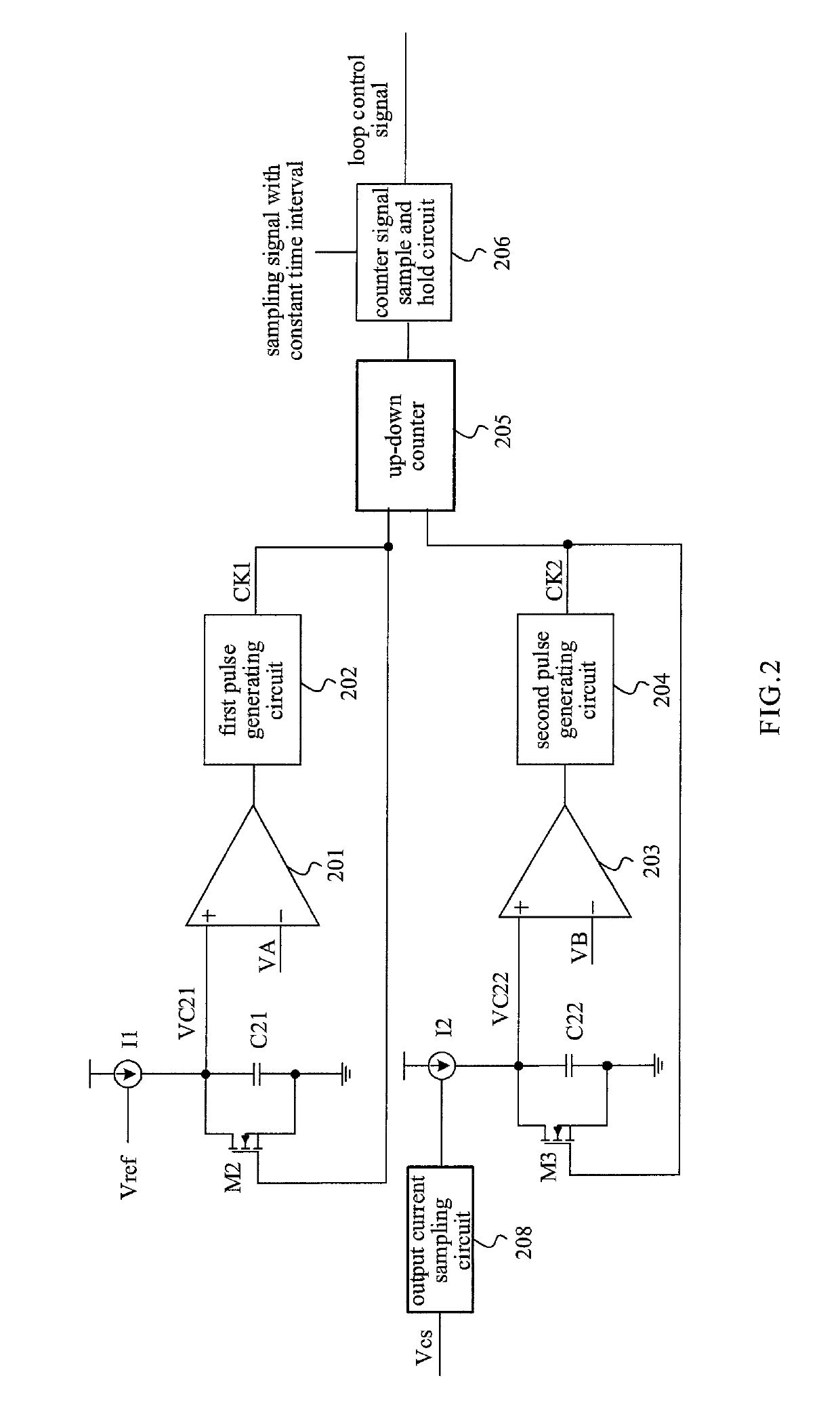
[0060]FIG. 2 is a schematic circuit diagram of an example error amplification apparatus according to a first embodiment of the present disclosure. The error amplification apparatus includes a first timing-current generating circuit I1, a first capacitor C21, a first switch M2, a first comparator 201, a first pulse generating circuit 202, a second timing-current generating circuit 12, a second capacitor C22, a second switch M3, a second comparator 203, a second pulse generating circuit 204, an up-down counter 205, a counter signal sample and hold circuit 206. The counter signal sample and hold circuit 206 provides a digital signal to control the circuit loop.
[0061]Specifically, as shown in FIG. 2, a reference voltage Vref controls the first timing-current generating circuit I1, the first timing-current generating circuit I1, one terminal of the first capacitor C21, and a source terminal of the first switch M2 are coupled to the positive input terminal of the first c...
second embodiment
A Second Embodiment
[0068]There are problems of circuit matching because the first capacitor C21 and second capacitor C22 are used in FIG. 2. Therefore, in the embodiment, the first capacitor C21 and second capacitor C22 is replaced by one capacitor C31, and the first timing-current generating circuit I1 and second timing-current generating circuit 12 is replaced by an error amplifier 401. The error amplifier 401 is typically a transconductance error amplifier.
[0069]FIG. 5 is a schematic circuit diagram of an example error amplification apparatus according to the second embodiment of the present disclosure. As shown in FIG. 5, the error amplification unit includes an error amplifier 401, a capacitor C31, a first switch 403, a first comparator 201, a second switch 404 and a second comparator 203.
[0070]The error amplifier 401 has two input terminals being respectively configured to receive a reference voltage Vref and an output current sampling signal, and an output terminal being coup...
third embodiment
A Third Embodiment
[0073]FIG. 6 is a schematic circuit diagram of an example error amplification apparatus according to the third embodiment of the present disclosure. As shown in FIG. 6, the first pulse generating circuit and the second pulse generating circuit of FIG. 5 are combined, i.e. a third pulse generating circuit 503 is employed. The second comparator 502 has an input terminal being coupled to the capacitor C31, VC and VD through selective switches. The first comparator 501 receives a first switching selection signal S1 and a second switching selection signal S2. The first switching selection signal S1 controls the third pulse generating circuit 503. The third pulse generating circuit 503 provides a pulse signal. The counter direction is controlled by the first switching selection signal S1, such that the first pulse CK1 and the second pulse CK2 are obtained from the pulse signal outputted from the third pulse generating circuit 503 to obtain the first pulse CK1 and the sec...
PUM
 Abstract
Description
Claims
Application Information