Error amplification apparatus and driving circuit including the same

Active Publication Date: 2019-08-22
HANGZHOU SILAN MICROELECTRONICS
View PDF0 Cites 6 Cited by
  • Summary
  • Abstract
  • Description
  • Claims
  • Application Information

AI Technical Summary

Benefits of technology

The error amplification apparatus described in this patent uses a pulse generating circuit and a counting unit to generate a compensation voltage based on the output voltage of an error amplification unit. This compensation voltage is then reflected by the counter value, which helps to filter out the ripple of alternating current. This reduces the capacitance of the compensation capacitor, simplifies the peripheral design, and eliminates the effect of moisture on the loop. Additionally, an up-down counter can be used to simplify the circuit and stabilize the loop. The technical effect of this patent is to improve the accuracy and stability of the error amplification apparatus.

Problems solved by technology

A compensation capacitor having such capacitance cannot be integrated into an integrated circuit.
In case the compensation capacitor is implemented outside the chip, the compensation capacitor is susceptible to the electrical leakage due to moisture, influencing the output current and making it difficult to implement a simple peripheral circuit.

Method used


Image

  • Error amplification apparatus and driving circuit including the same
  • Error amplification apparatus and driving circuit including the same
  • Error amplification apparatus and driving circuit including the same

Examples


first embodiment

A First Embodiment

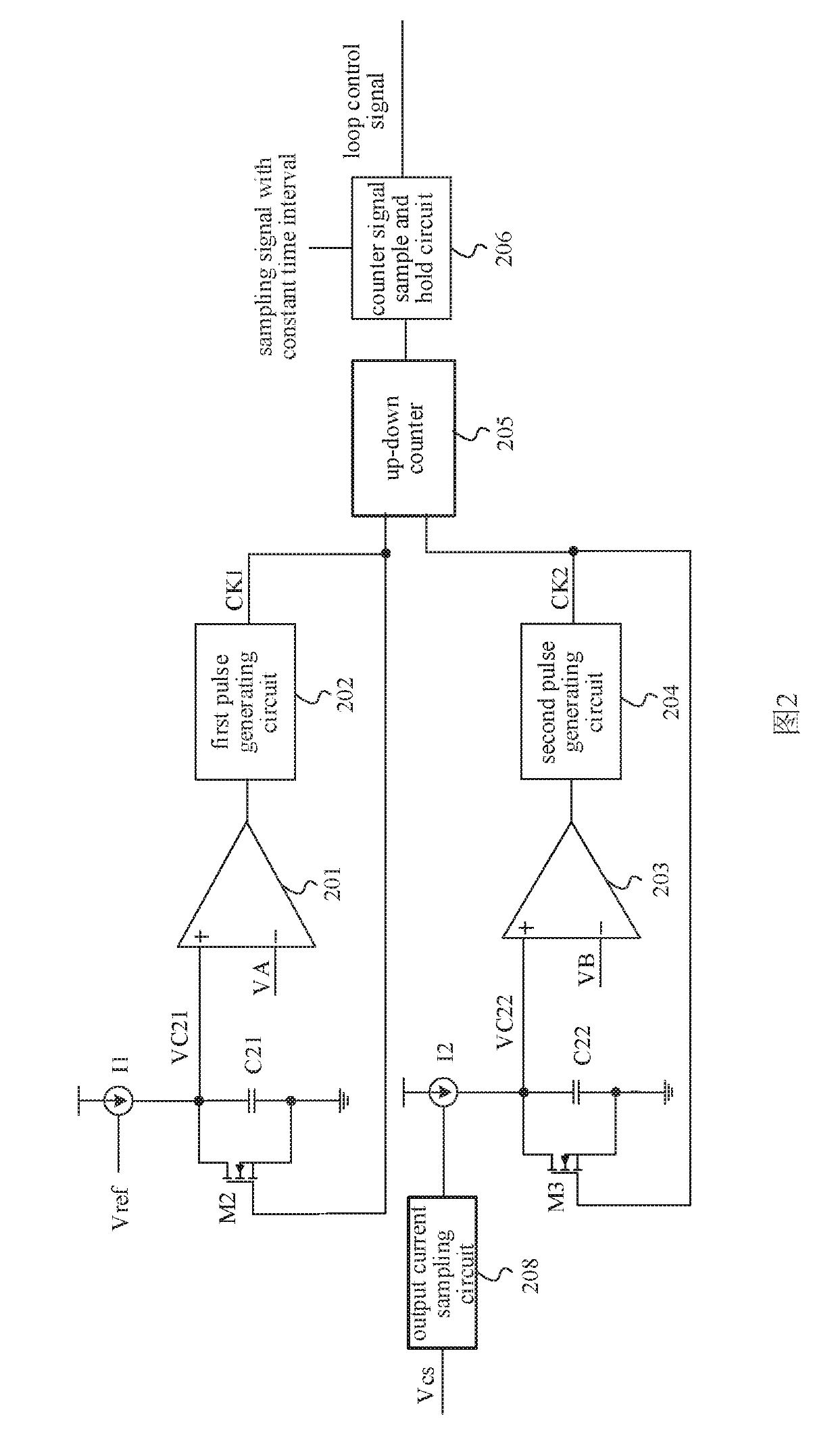
[0060]FIG. 2 is a schematic circuit diagram of an example error amplification apparatus according to a first embodiment of the present disclosure. The error amplification apparatus includes a first timing-current generating circuit I1, a first capacitor C21, a first switch M2, a first comparator 201, a first pulse generating circuit 202, a second timing-current generating circuit I2, a second capacitor C22, a second switch M3, a second comparator 203, a second pulse generating circuit 204, an up-down counter 205, a counter signal sample and hold circuit 206. The counter signal sample and hold circuit 206 provides a digital signal to control the circuit loop.

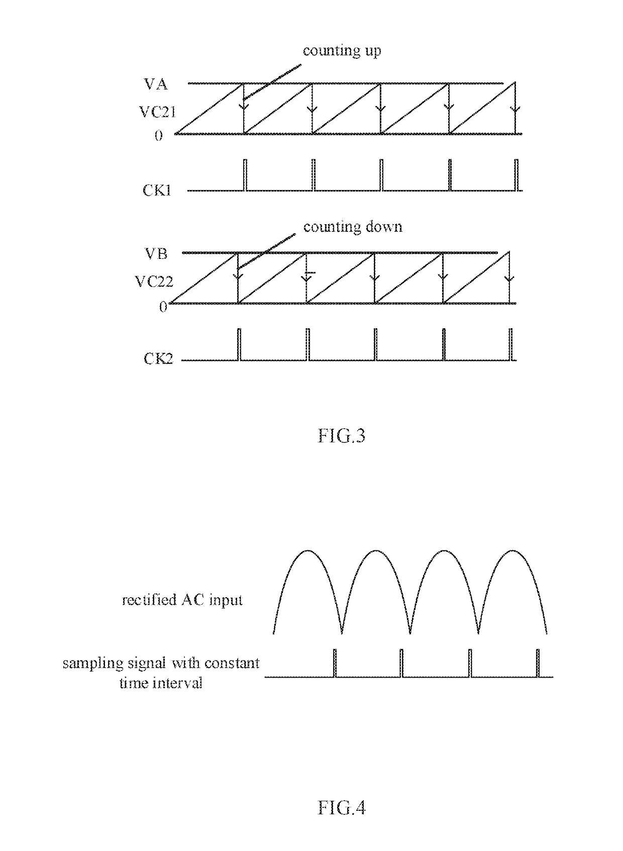
[0061]Specifically, as shown in FIG. 2, a reference voltage Vref controls the first timing-current generating circuit I1, the first timing-current generating circuit I1, one terminal of the first capacitor C21, and a source terminal of the first switch M2 are coupled to the positive input terminal of the first c...

second embodiment

A Second Embodiment

[0068]There are problems of circuit matching because the first capacitor C21 and second capacitor C22 are used in FIG. 2. Therefore, in the embodiment, the first capacitor C21 and second capacitor C22 is replaced by one capacitor C31, and the first timing-current generating circuit I1 and second timing-current generating circuit I2 is replaced by an error amplifier 401. The error amplifier 401 is typically a transconductance error amplifier.

[0069]FIG. 5 is a schematic circuit diagram of an example error amplification apparatus according to the second embodiment of the present disclosure. As shown in FIG. 5, the error amplification unit includes an error amplifier 401, a capacitor C31, a first switch 403, a first comparator 201, a second switch 404 and a second comparator 203.

[0070]The error amplifier 401 has two input terminals being respectively configured to receive a reference voltage Vref and an output current sampling signal, and an output terminal being coup...

third embodiment

A Third Embodiment

[0073]FIG. 6 is a schematic circuit diagram of an example error amplification apparatus according to the third embodiment of the present disclosure. As shown in FIG. 6, the first pulse generating circuit and the second pulse generating circuit of FIG. 5 are combined, i.e. a third pulse generating circuit 503 is employed. The second comparator 502 has an input terminal being coupled to the capacitor C31, VC and VD through selective switches. The first comparator 501 receives a first switching selection signal S1 and a second switching selection signal S2. The first switching selection signal S1 controls the third pulse generating circuit 503. The third pulse generating circuit 503 provides a pulse signal. The counter direction is controlled by the first switching selection signal S1, such that the first pulse CK1 and the second pulse CK2 are obtained from the pulse signal outputted from the third pulse generating circuit 503 to obtain the first pulse CK1 and the sec...


PUM


Abstract

The disclosure relates to an error amplification apparatus and a driving circuit including the error amplification apparatus. In the error amplification apparatus according to the disclosure, a pulse generating circuit generates a first pulse and a second pulse in accordance with an output voltage of an error amplification unit, a counting unit being coupled to the pulse generating circuit counts the first pulse and the second pulse, and generates a loop control signal representing a compensation voltage based on the count. The disclosure utilizes the counting unit to digitize the compensation voltage, and the counter value can reflect the compensation voltage, so that the variation of the loop control signal in the AC cycle of 50 Hz or 60 Hz is controlled to be little, thereby filtering out the ripple of AC of 50 Hz or 60 Hz. In this manner, the capacitance of the compensation capacitor is reduced so that the compensation capacitor can be integrated inside the IC chip, thereby simplifying the peripheral design, and eliminating the influence on the loop by the electrical leakage current due to moisture.

Description

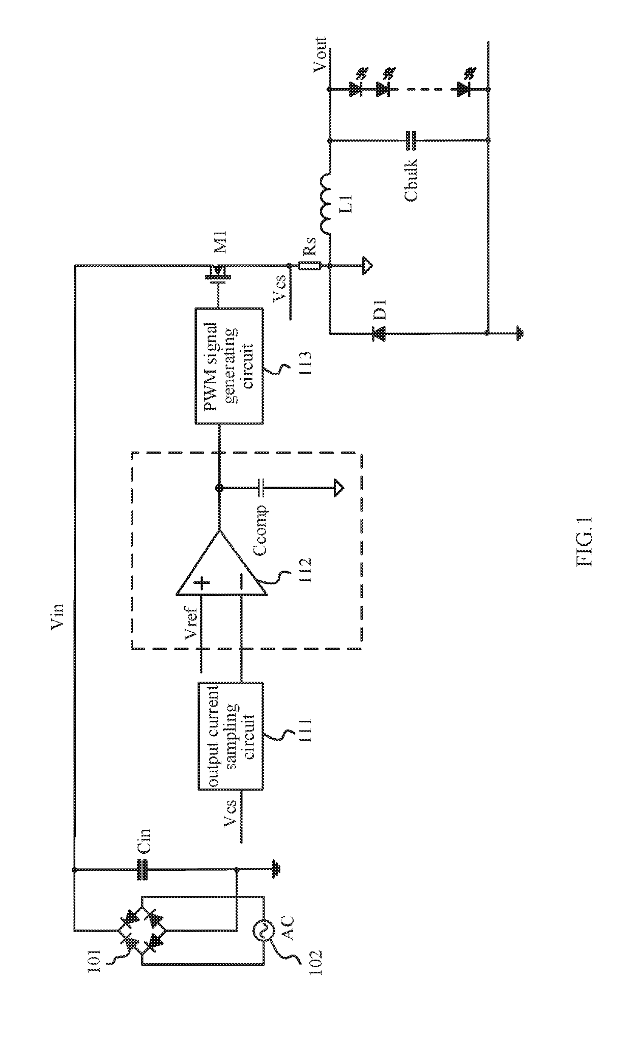
CLAIM OF PRIORITY[0001]This application is a Section 371 National Stage Application of International Application No. PCT / CN2016109328, filed on Dec. 9, 2016, entitled “ERROR AMPLIFICATION APPARATUS AND DRIVING CIRCUIT INCLUDING THE SAME”, which claims priority to Chinese Application No. 201510917062.3, filed on Dec. 10, 2015, entitled as “error amplification apparatus and driving circuit including the same”, which are hereby incorporated by reference.BACKGROUND OF THE DISCLOSUREField of the Disclosure[0002]The disclosure relates to an error amplification apparatus and a driving circuit including the same.Description of the Related Art[0003]A conventional LED constant-current driving circuit with buck topology is shown in FIG. 1, the LED constant-current driving circuit is AC (Alternating Current) powered and has a Power Factor Correction (PFC) function. It typically includes an AC input rectifier circuit 101, an AC input source 102, an input capacitor Cin, an inductor L1, an power s...

Claims


Application Information

Patent Timeline
IPC IPC(8): H02M1/08H02M3/157H02M1/14H05B44/00
CPCH02M1/08H02M3/157H02M1/14H05B33/0815H03F3/45941H05B45/3725H02M1/0025H02M1/4225H03F3/45H05B45/375Y02B20/30Y02B70/10H02M1/0009
Inventor YAO, YUNLONGWU, JIANXING
Owner HANGZHOU SILAN MICROELECTRONICS
Why Eureka
Try Eureka