Depth wheels

a technology of depth wheels and scoring disks, applied in the field of farming, can solve the problems of affecting the quality of depth wheels, etc., and achieves the effects of reducing the number of depth wheels

Active Publication Date: 2019-10-01
ROSENBOOM LYN A
View PDF8 Cites 4 Cited by
  • Summary
  • Abstract
  • Description
  • Claims
  • Application Information

AI Technical Summary

Benefits of technology

[0012]The row implement of this invention has at least one depth wheel that is less likely to skid and cause a build up of trash.

Problems solved by technology

After a crop is harvested, the soil is often compacted, depleted of nutrients, and full of crop residue and other debris.
Depth wheels attached to independently rotating scoring disks suffer from two problems.
First, trash tends to build up along the right angle corner where the depth wheel meets the scoring disk.
Second, the independently rotating scoring disks with attached depth wheels tend to skid rather than rotate, especially in wet fields or fields having a large amount of trash.
As they skid, trash builds up and causes plugging in and between the row implements.
The disadvantage of pneumatic rubber depth wheels is that they wear out and must be replaced periodically.
The disadvantage of these independently rotating steel depth wheels is that they tend to skid rather than rotate.
As they skid, trash builds up and causes plugging in and between the row implements.

Method used


Image

  • Depth wheels
  • Depth wheels
  • Depth wheels

Examples


Embodiment Construction

[0016]1. The Invention in General

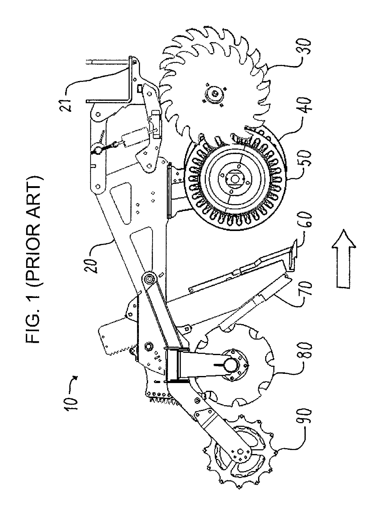
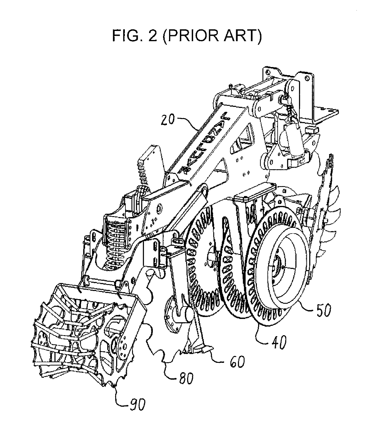
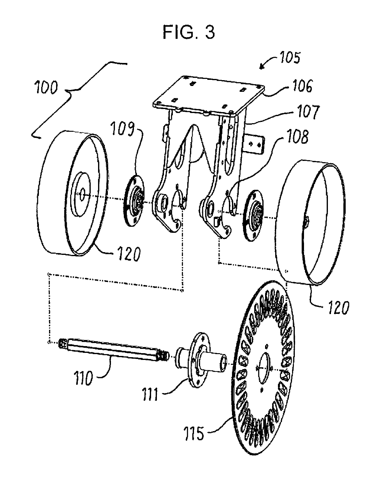
[0017]This invention is best understood by reference to the drawings. Referring to FIG. 3, a preferred embodiment of the disk and depth wheel assembly 100 of this invention comprises a bracket 105, a shaft 110, a disk 115 attached to the shaft, and two depth wheels 120 mounted onto the shaft. The other components of a row implement are shown in FIGS. 1 and 2 and are omitted from FIG. 3 for clarity. The disk and depth wheel assembly is mounted on a row implement ahead of the knife. The disk and depth wheel assembly can be used in place of the disks and depth wheels assembly shown in FIGS. 1 and 2. The disk and depth wheel assembly of this invention can also be used in combination with other disks if desired.

[0018]2. The Bracket

[0019]The bracket 105 is attachable to the frame of the row implement. The preferred embodiment of the bracket has a horizontal top plate 106 and two spaced apart vertical plates 107. Each of the vertical plates has a semi-circu...


PUM


Abstract

A row implement has a disk and depth wheel assembly attached to the frame. The assembly includes: (i) a bracket; (ii) a horizontal freely rotating shaft; (iii) a disk attached to the shaft; and (iv) a depth wheel attached to the shaft on either side of the disk, so the shaft, disk, and the depth wheel rotate together.

Description

CROSS-REFERENCE TO RELATED APPLICATION[0001]This application claims the benefit of U.S. Provisional Application Ser. No. 62 / 459,643, Feb. 16, 2017.FIELD OF THE INVENTION[0002]This invention relates to farming. More particularly, this invention relates to row implements for the tillage, planting, and fertilization of farmland.BACKGROUND OF THE INVENTION[0003]It is well known that crops such as corn and soybeans grow best in soil that is loose, rich in nutrients, and free of debris. After a crop is harvested, the soil is often compacted, depleted of nutrients, and full of crop residue and other debris. To restore the soil to optimal conditions, the soil is often tilled immediately before planting. Tilling is also known as cultivating or plowing (also spelled “ploughing”). The soil may also be tilled immediately after harvest. The conventional method of tillage is to treat the entire field. More recently, it has become popular to treat only the narrow strips of soil that will contain t...

Claims


Application Information

Patent Timeline
Patent Type & Authority Patents(United States)
IPC IPC(8): A01B76/00A01B49/02A01B15/16A01B5/04A01B15/14B60C7/06
CPCA01B15/16A01B5/04A01B76/00A01B15/14A01B49/027B60C2200/08B60C7/06B60C7/00
Inventor ROSENBOOM, LYN A.
Owner ROSENBOOM LYN A
Why Eureka
Try Eureka