An anti-mud bag PDC drill bit with pits on the surface of the runner groove

A technology of runner grooves and pits, which is used in drill bits, earth-moving drilling, drilling equipment, etc., to reduce drilling costs, prevent adhesion, and reduce adhesion.

Active Publication Date: 2016-04-06
SOUTHWEST PETROLEUM UNIV +2
View PDF6 Cites 0 Cited by
  • Summary
  • Abstract
  • Description
  • Claims
  • Application Information

AI Technical Summary

Problems solved by technology

[0004] The purpose of the present invention is to overcome the deficiencies of the above-mentioned prior art, provide a kind of anti-balling PDC drill bit with dimples on the surface of the flow channel, solve the problem of balling of the PDC bit, improve drilling efficiency, and reduce drilling costs

Method used


Image

  • An anti-mud bag PDC drill bit with pits on the surface of the runner groove
  • An anti-mud bag PDC drill bit with pits on the surface of the runner groove
  • An anti-mud bag PDC drill bit with pits on the surface of the runner groove

Examples


Embodiment 1

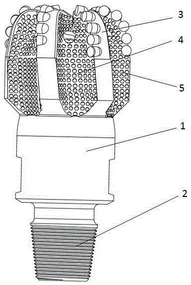
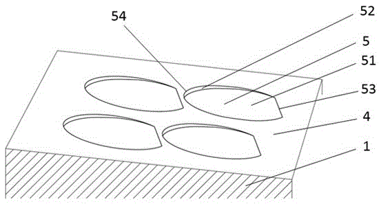
[0040] see Figure 1 to Figure 4As shown, a kind of anti-mud bag PDC drill bit with dimples on the surface of the flow channel includes a drill body 1. The lower part of the drill body 1 is provided with a threaded joint 2 for connecting the drill pipe, and the upper part is provided with several blades 3. Between the blades 3 The groove between them forms the runner groove 4 of the drill bit. The surface of the runner groove 4 is provided with at least two pits 5. The pit 5 is composed of a pit bottom 51 and a pit side 52. The pit bottom 51 It extends directly from the bottom of the pit to the surface of the runner groove 4 . The slope angle α of the bottom surface 51 of the pit ≤ 40°; the ratio of the projected area S1 of the side surface 52 of the pit to the original surface of the runner groove 4 and the projected area S2 of the bottom surface 51 of the pit to the original surface of the runner groove 4 is equal to The range is S1:S2≤1:3. The angle between the bottom sur...

Embodiment 2

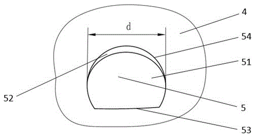
[0045] see image 3 with Figure 4 , The difference between this embodiment and Embodiment 1 is that the depth c of the pit 5 is 0.3-5 mm, and the length d≥2 mm.

[0046] This range of depth and length of the pit 5 is the easiest to process. If the length and depth of the pit 5 are too small, the processing difficulty will be very great.

[0047] It should be explained that the so-called length of the pit 5 refers to the largest profile dimension in the transverse or longitudinal direction of the pit.

Embodiment 3

[0049] see Figure 5 The difference between this embodiment and the first embodiment is that the adjacent dimples 5 on the runner groove 4 intersect. Small cuttings adhesion and anti-mudbag effect.


PUM


Abstract

The invention discloses a balling-resistant PDC (polycrystalline diamond compact) drill bit with pits in the surfaces of flow passages. The balling-resistant PDC drill bit comprises a drill bit body, the lower portion of the drill bit body is provided with a screwed joint connected with a drill rod, the upper portion of the drill bit body is provided with a plurality of blades, grooves between the blades form flow passage grooves of the drill bit, at least two pits are formed in the surface of each flow passage groove, and the bottom surface of each pit extends upwards from the deepest position of the pit bottom to the inclined plane of the surface of the corresponding flow passage groove. By the balling-resistant PDC drill bit, adhesion tendency of rock debris in the flow passage grooves is reduced obviously, and the flow passages are prevented from being blocked to achieve the purpose of resisting balling, so that drilling efficiency of the drill bit is improved, service life of the drill bit is prolonged, and drilling cost is lowered.

Description

technical field [0001] The invention belongs to the technical fields of drilling equipment such as petroleum and natural gas, mining engineering, building foundation engineering construction, geology, and hydrology, and in particular relates to a mud-packing-resistant PDC drill bit with pits on the surface of the flow channel. Background technique [0002] PDC bit is a kind of drill bit that uses polycrystalline diamond composite sheet (that is, PDC tooth, also referred to as cutting tooth or tooth) to scrape or shear rock. It is one of the main rock-breaking tools used in drilling engineering today. , especially in the drilling of medium and soft formations, PDC bits are used the most. In order to make the cutting structure and hydraulic structure of the drill bit achieve better working results, when designing and manufacturing the drill bit, the PDC teeth are usually divided into several groups according to certain rules, and the PDC teeth of the same group are consolidate...

Claims


Application Information

Patent Timeline
Patent Type & Authority Patents(China)
IPC IPC(8): E21B10/46
Inventor 林敏杨迎新陈炼曾力哲徐强任海涛周谧包泽军周春晓
Owner SOUTHWEST PETROLEUM UNIV
Why Eureka
Try Eureka