Headrest folding device

a folding device and headrest technology, applied in the direction of headrests, vehicle components, vehicle arrangements, etc., can solve the problems of large load, noise generation, difficult smooth operation, etc., and achieve the effect of soft and smooth operation of the release lever, increased strength, and smooth operation

Active Publication Date: 2019-10-01
WOOBO TECH
View PDF23 Cites 6 Cited by
  • Summary
  • Abstract
  • Description
  • Claims
  • Application Information

AI Technical Summary

Benefits of technology

[0027]According to a headrest folding device of the present invention, there are following effects.
[0028]The lock link which is directly locking the stay is released through the release lever and the ratchet so that the release lever is operated on the ratchet which is indirectly connected to the stay, therefore, a user can softly and smoothly operate the release lever without applying a large force thereto. Furthermore, since the ratchet and the stay are indirectly connected to each other, the strength can be increased through the shape change of the ratchet without changing the shape of the circular cross-section of the stay.
[0029]Also, through the engagement of the ratchet with the lock link which is capable of adjusting the rotating radius of the stay, there are effects of a smooth operation due to the indirect locking with the stay, reduction in the externally exposed area of the slot in the seat back through the change of the rotation radius of the stay, reduction in the number of additional components by utilizing the lock link which is an existing component, and the like.
[0030]Particularly, due to the mutual reaction of the mountain peak shaped groove of the lock link and the mountain peak shaped ridge of the ratchet, the rotation of the ratchet with respect to the lock link is smoothly performed along the mountain peak shaped inclined surface so that the smooth operation of the release lever is more facilitated, and similarly, positioning of the lock link towards the lock position is performed along the mountain peak shaped inclined surface, and the docking of the lock link is smoothly performed thereby.
[0031]Also, an open slot is formed in the main bracket so that the other end of the first twisted coil spring is disposed in the open slot as it is spread, therefore, the assembling becomes very easy when fixing it to the horizontal bar of the stay.
[0032]Also, since the length of the release lever from front to rear direction is long, a slot is formed in the front plate of the main bracket so that the stopper protrusion is disposed in the slot, thus a space allowing rotation is secured, so the length of the main bracket from front to rear can be reduced to minimum.

Problems solved by technology

In this way, since the braking member or the stopper must directly release the holding of the stay rod in order to switch from the unfolding state to the folding state, therefore a large load is imposed thereon making smooth operation difficult and generating noise too.
Also, since the holding member 40 or the stopper 130 is directly holding the stay, there is limitation in enhancing the strength of the headrest under the state of locking.
Moreover, even the thickness and the size of the stay are changed, it is not practical since the weight and the size will be increased thereby.
Therefore, since the rotation amount of such pivot type rotation is large, the length of the slot in the seat back along the front to rear direction becomes longer, which is not desirable in the aspects of appearance.

Method used


Image

  • Headrest folding device
  • Headrest folding device
  • Headrest folding device

Examples


embodiment 1

tay for Pulling

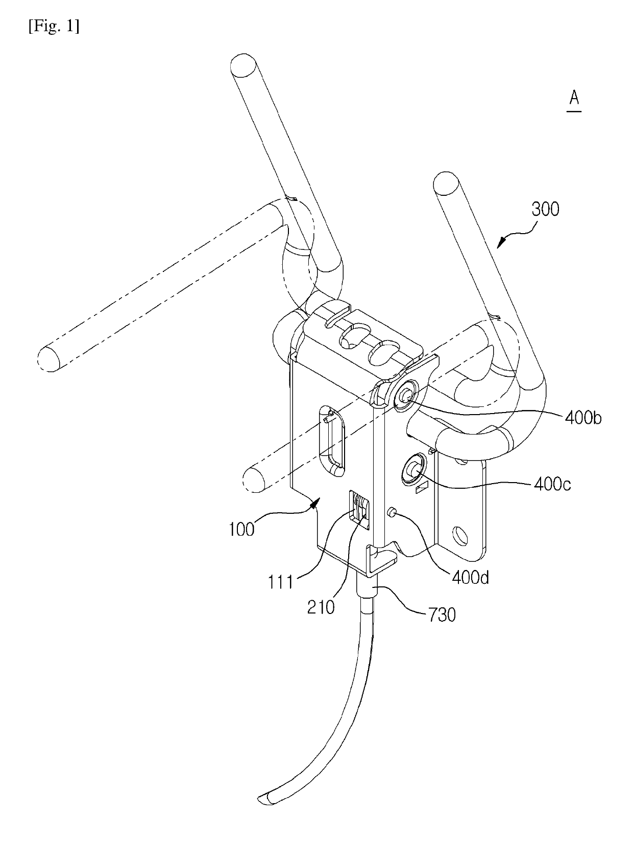
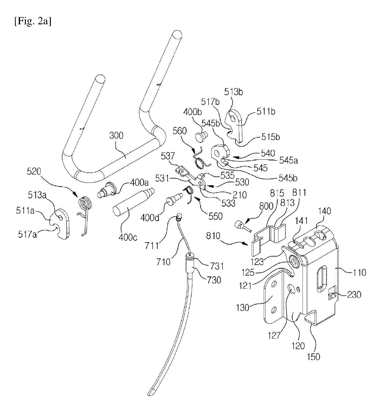
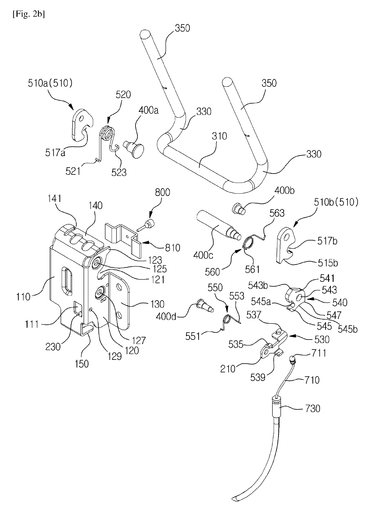
[0051]FIG. 1 is an assembled perspective view illustrating a headrest folding device according to the preferred first exemplary embodiment of the present invention; FIGS. 2a and 2b are the exploded perspective views of FIG. 1 viewing from the left side and the right side respectively; FIGS. 3 and 4 are the assembled rear views illustrating the upright (unfolding) position and the folding position of the stay respectively; FIG. 5 is a side view when the stay is in the upright (unfolding) position; FIG. 6 is a side view illustrating a state wherein the lock is being released when the pulling member is pulled down; and FIG. 7 is a side view when the stay is in the folding position.

[0052]As illustrated in FIGS. 1 to 4, a headrest folding device A according to the first exemplary embodiment of the present invention comprises: a main bracket 100 mounted in a seat back; a stay 300, mounted in a headrest, rotated with respect to the main bracket so as to be moved between the ...

embodiment 2

ain Bracket for Pulling

[0133]FIGS. 8 and 9 are a rear view and a perspective view respectively illustrating the headrest folding device according to the preferred second exemplary embodiment of the present invention, and FIG. 10 is a perspective view illustrating the essential parts of FIG. 9.

[0134]The configuration of the headrest folding device B according to the second exemplary embodiment is almost same as that of the headrest folding device according to the first exemplary embodiment except that a main bracket 100 is mounted in the headrest HR, and a stay 300′ is mounted in the seat back SB.

[0135]That is, the headrest folding device B according to the second exemplary embodiment is same as the headrest folding device according to the first exemplary embodiment A with flipped upside down.

[0136]Due to the flipped upside down configuration, the main bracket 100 is located in the upper side, therefore the pulling member 700 is also located in the upper side.

[0137]In order to guide ...

embodiment 3

ain Bracket for Button

[0150]FIGS. 11 and 12 are a rear view and a perspective view respectively illustrating the headrest folding device according to the preferred third exemplary embodiment of the present invention; FIG. 13 is a perspective view illustrating the essential parts of FIG. 12; FIG. 14 is a perspective view illustrating the release lever of FIG. 13; and FIG. 15 is an exploded perspective view illustrating the button unit.

[0151]The configuration of the headrest folding device C according to the third exemplary embodiment is almost same as that of the headrest folding device according to the second exemplary embodiment B, however, there is a difference in that the operating member 700 of a release lever 530′ is implemented by a button unit 700′.

[0152]In addition, for the detailed structure and description of the button unit 700′, refer to Korea Registered Patent No. 10-1428664 that had been filed earlier by the applicant of this application.

[0153]That is, the release leve...


PUM


Abstract

The present invention relates to a headrest folding device, more particularly, to a headrest folding device wherein a ratchet is connected between a release lever and a lock link which maintains the unfolding (upright) of a headrest, so that the operation of the release lever is not directly transferred to the lock link, but rather indirectly transferred to the lock link through the ratchet, thereby smoothing the operation of the release lever.

Description

[0001]This application is the national phase entry of international patent application No. PCT / KR2016 / 011336 filed Oct. 11, 2016 and claims the benefit of Korean patent application No. 10-2015-0162006, filed Nov. 18, 2015, the disclosures of which are incorporated herein by reference in their entirety.TECHNICAL FIELD[0002]The present invention relates to a headrest folding device, more particularly, to a headrest folding device wherein a ratchet is connected between a release lever and a lock link which maintains the unfolding (upright) of a headrest, so that the operation of the release lever is not directly transferred to the lock link, but rather indirectly transferred to the lock link through the ratchet, thereby smoothing the operation of the release lever.BACKGROUND ART[0003]A headrest folding device of the prior art has been suggested, for example, as disclosed in the Patent Literature 1 (Korea Registered Patent No. 10-1080313) that had been filed earlier by the applicant of ...

Claims


Application Information

Patent Timeline
Patent Type & Authority Patents(United States)
IPC IPC(8): B60N2/847B60N2/874B60N2/856B60N2/844B60N2/80
CPCB60N2/856B60N2/847B60N2/80B60N2/874B60N2/844
Inventor JEONG, HAE IL
Owner WOOBO TECH
Why Eureka
Try Eureka