Brake installation measurement and verification system

a technology for installing and verifying systems, applied in the field of air brakes, can solve problems such as affecting vehicle performance, reducing the service life of vehicles,

Active Publication Date: 2019-10-01
VAN HAECKE LEONARD
View PDF16 Cites 8 Cited by
  • Summary
  • Abstract
  • Description
  • Claims
  • Application Information

AI Technical Summary

Benefits of technology

[0007]Therefore, a general object of this invention is to provide a pushrod measurement and verification system that enables an automotive technician to properly determine an optimal cutback length and position at which to cut or sever a pushrod that extends away from a brake chamber;
[0009]Still another object of this invention is to provide a pushrod measurement and verification system, as aforesaid, that provides measurement and verification tools that remove the guesswork of the complex job of replacing brake assemblies on semi-trucks.

Problems solved by technology

If the brake geometry is out of a predetermined range, vehicle performance may be affected and the components of the assembly may be shortened.
Proper brake geometry is critical as out of adjustment brakes can cause the vehicle to be taken out of service by law enforcement or, worse yet, lead to a traffic accident.
Specifically, repair technicians sometimes make crucial errors when setting up the geometry of a brake system.
For instance, the brakes may instantly and unexpectedly lock up if a pushrod is cut too long or the brakes may not work at all if the pushrod is cut too short.
Technicians often just “eyeball” the proper pushrod length which can lead to disaster on the highway when trying to stop a truck weighing 80,000 pounds.
Although presumably effective for their intended purposes, the existing devices and methods for installing and configuring components of a brake assembly coupled to and associated with a pushrod remain confusing and prone to error.
The process is made even more difficult for a technician lying underneath a truck.

Method used


Image

  • Brake installation measurement and verification system
  • Brake installation measurement and verification system
  • Brake installation measurement and verification system

Examples


Embodiment Construction

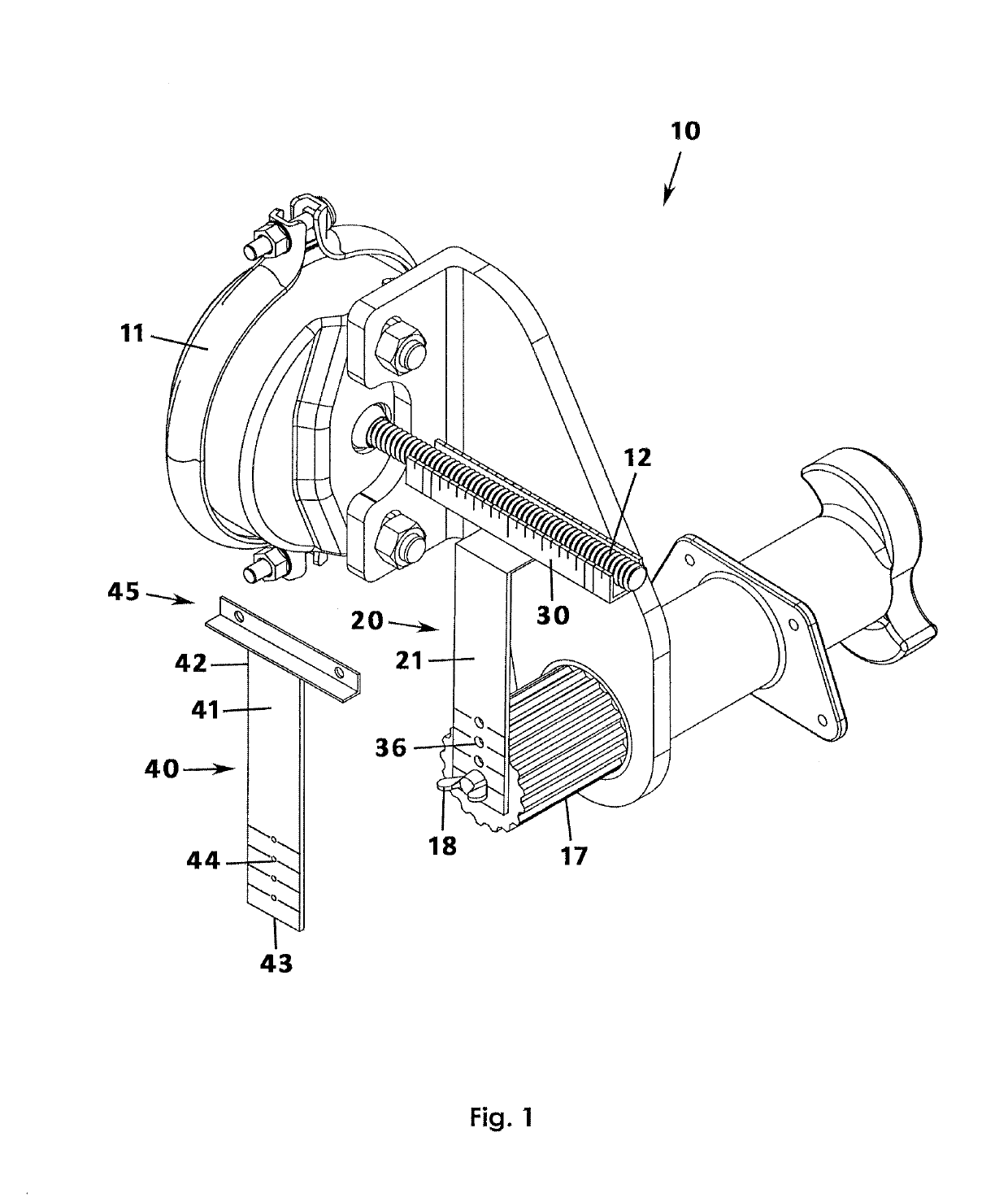
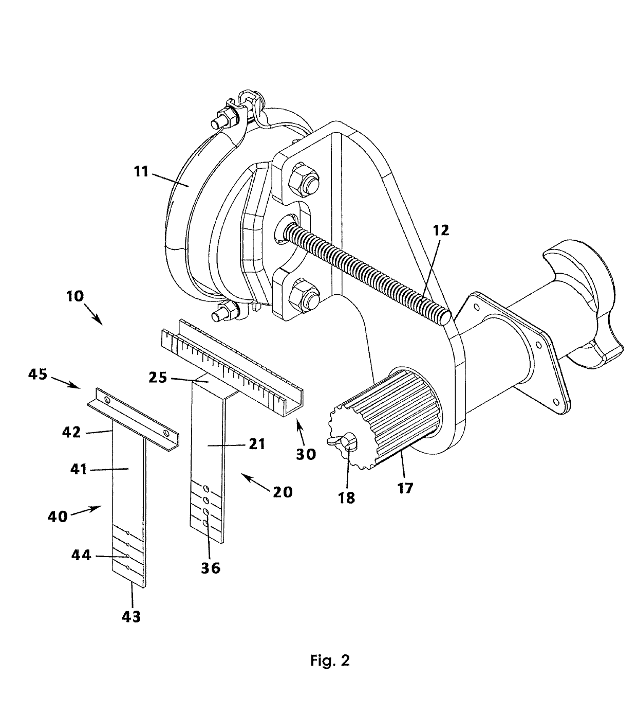
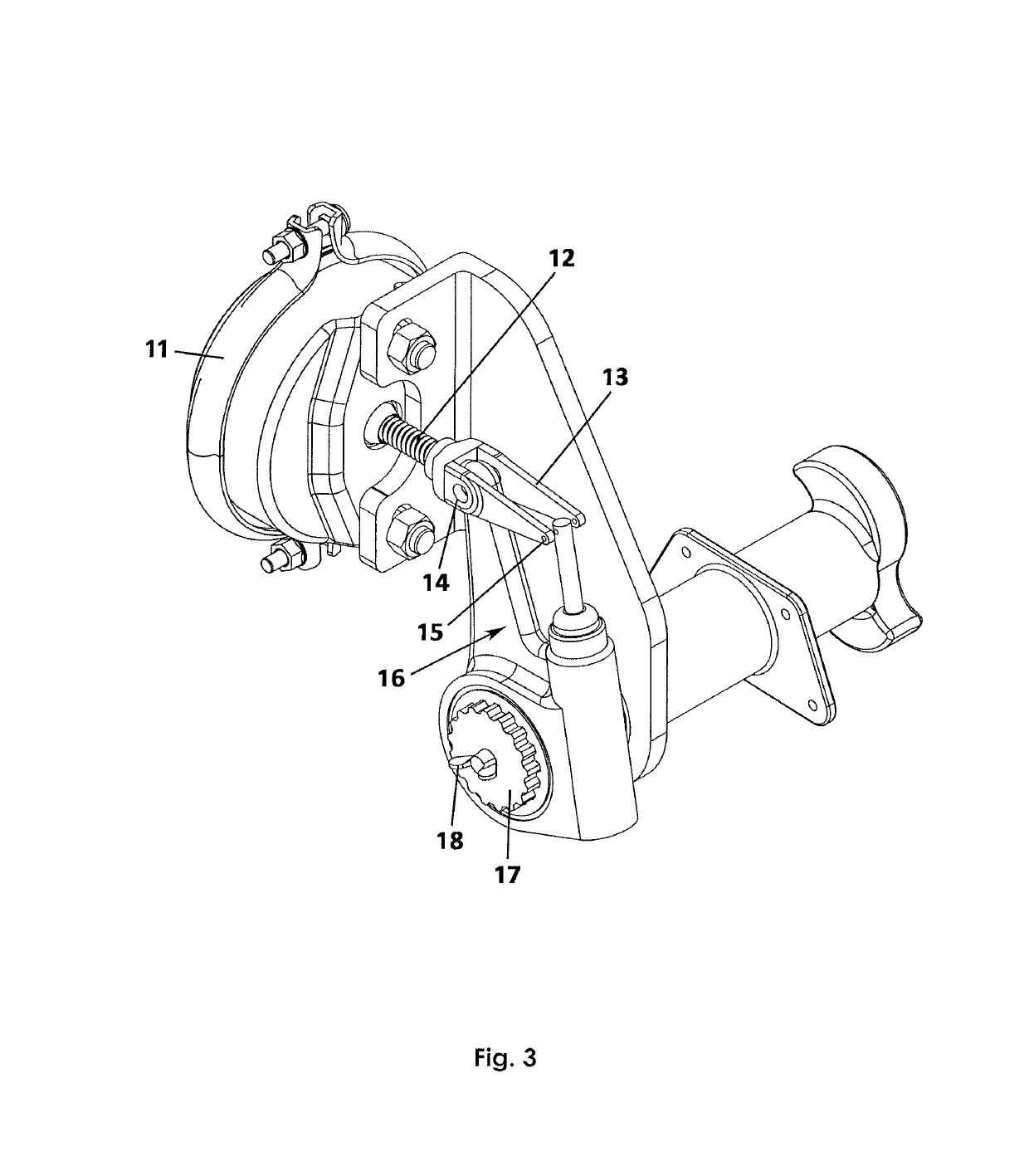
[0024]A pushrod measurement and verification system will now be described with reference to FIGS. 1 to 13 of the accompanying drawings. The pushrod measurement and verification system 10 includes a measurement member 20 and a verification member 40 for use in a method of measuring, marking, and cutting a pushrod 12 of an air brake assembly.

[0025]The accompanying drawings are best understood with an understanding of an air braking system with which the present invention is associated. Air brakes are typically used on heavy equipment and, more particularly, on semi-trucks for selectively allowing or stopping the truck's wheels from rotating. Specifically, an S-cam braking system is utilized and will be referenced herein. In a generalized explanation of an air-brake assembly, when a driver presses on a brake pedal inside the cab of the truck, air may be pushed into a brake chamber 11 causing an outward linear movement of a pushrod 12. The pushrod 12 may be coupled to a clevis 13 which ...


PUM


Abstract

A pushrod measurement and verification system for determining a cutback length at which to sever a pushrod extending from a brake chamber so that a slack adjuster is properly mounted in an air brake system. The system includes a measurement member having a body member that includes opposed lower and upper ends, the body member having a thin and planar configuration. The body member defines a plurality of holes adjacent the lower end corresponding to sizes of the slack adjuster to be installed. The measurement member includes a cradle portion mounted to the upper end of the body member, the cradle portion having a bottom wall and a pair of side walls extending upwardly from the bottom wall and defining an open top, the cradle portion configured to cradle a pushrod. A front surface of the cradle portion includes measurement indicia for determining a cutback length of the pushrod.

Description

BACKGROUND OF THE INVENTION[0001]This invention relates generally to air brakes for heavy equipment and, more particularly, to a system having at least measurement and verification tools for determining a proper length at which to cut a pushrod for proper setup of a brake replacement procedure.[0002]Heavy equipment, including semi-trucks, typically include air brakes as the primary means for stopping rotation of its wheels. An air brake system is a complex mechanical assembly and must be kept in good working condition and in proper alignment with all of the air brake components of the truck to avoid component failure and potential injury and cost. More particularly, the pushrods within a brake assembly should be cut to a specific length to work efficiently with the slack adjusters and, thereafter, the S-cams that actually cause a braking action. If the brake geometry is out of a predetermined range, vehicle performance may be affected and the components of the assembly may be shorte...

Claims


Application Information

Patent Timeline
Patent Type & Authority Patents(United States)
IPC IPC(8): G01B5/02G01B5/00B60T17/22
CPCG01B5/0028B60T17/221B60T17/081B60T17/088
Inventor VAN HAECKE, LEONARD
Owner VAN HAECKE LEONARD
Why Eureka
Try Eureka