
Robotic gripping assist

Active Publication Date: 2019-10-22
UNITED ARAB EMIRATES UNIVERSITY
View PDF41 Cites 16 Cited by
  • Summary
  • Abstract
  • Description
  • Claims
  • Application Information

AI Technical Summary

Benefits of technology

This patent describes a device that attaches a grip to a user's hand and arm using a mitten and arm wrap, which are connected directly to the grip. The device also includes straps that wrap around the mitten and arm wrap for added security. Once the device is attached, the user can continue to function normally with the benefit of added grip strength. The technical effect of this invention is to provide a convenient and effective way to increase a user's grip strength and improve their overall performance in various activities.

Problems solved by technology

However, wearable robotic support arms have both hardware and software limitations.
One major software obstacle occurs when the robot does not efficiently define and interact with the activities and purposes of the wearer.

Method used


Image

  • Robotic gripping assist
  • Robotic gripping assist
  • Robotic gripping assist

Examples


first embodiment

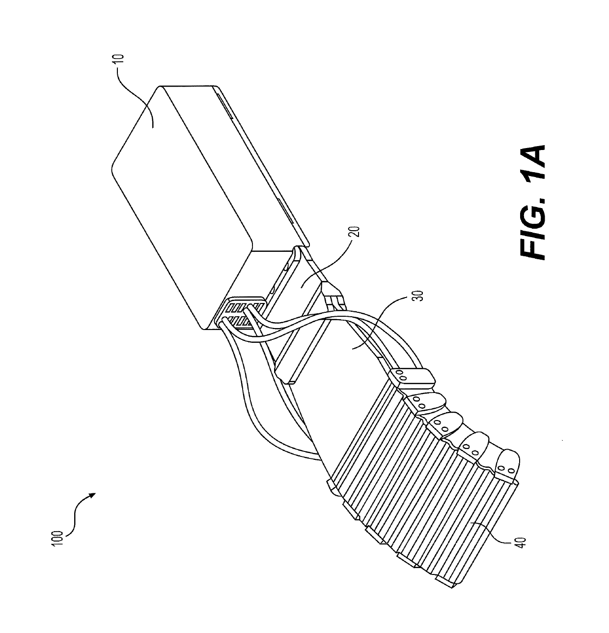
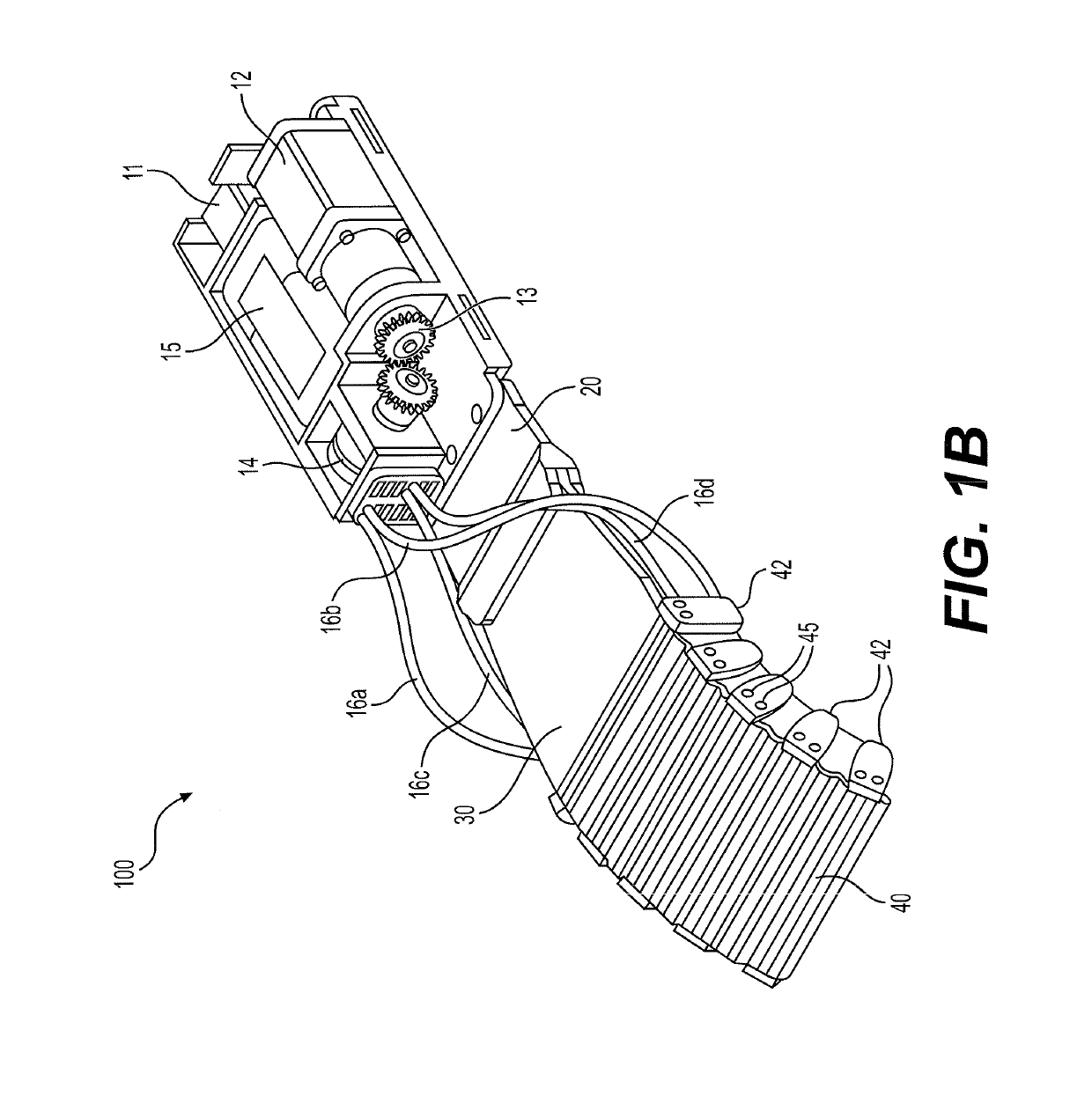
[0038]FIG. 1A shows the RGA 100. The RGA 100 includes an arm box 10 connected to a base member 20, which is attached to a bending member 40 through an intermediate member 30. As seen in FIG. 1B, which shows the arm box 10 without its cover, the arm box 10 houses a power switch 11, a motor 12, a gear train 13, a spool 14, and a battery 15. Four wires 16a, 16b, 16c, and 16d are strung through support elements 42 attached to the sides of the bending member 40 along its length.

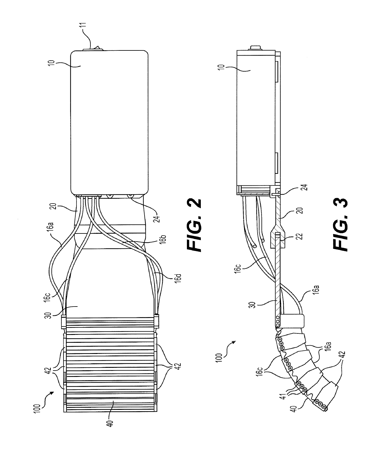
[0039]FIGS. 2 and 3 are top and side views, respectively, of the RGA 100. FIG. 2 shows the bending member 40 is a corrugated, flexible belt having a rectangular shape (i.e., substantially uniform width) with support members 42 attached to opposing sides. As seen in FIG. 3, the tops of the support members 42 are connected to the bending member 40 and may be evenly spaced along its length. Two of the wires 16a, 16b are strung through the bottom of the support elements 42, one on each side of the bending member 40, a...

second embodiment

[0044]FIG. 3 also shows a side view of the bending member 40. As seen in FIG. 3, the rigid rods 41 provide rigid attachment points for the support members 42. Accordingly, the bending forces from the support members 42 are evenly distributed along the width of the bending member 40 by the rigid rods 41. By alternating the flexible wave portions of the belt 43a and the sheath portions 43b containing the rigid rods 41, the corrugated bending member 40 is provided with the necessary flexibility along its length for moving from a straight to a gripping position, while having the stability to prevent bending in a width direction and evenly distributing the forces from the support members 42. In addition to flexing downward when moving from a straight to a gripping position, the bending member 40 also experiences compression and extension along its length. The multiple wavelength wave portions between the sheath portions 43b allow the bending member 40 to compress and extend during operat...


PUM


Abstract

The robotic gripping assist (“RGA”) provides a user with additional grip strength by supporting and forcefully pushing a user's fingers and hand to a gripping position. A motor, controller, and power source are supported on a user's forearm and act as a source for the forced movement. A bending member is worn on the back of a user's hand. The motor draws in or lets out wires that cause the bending member to bend or straighten. By bending the bending member, through rotating the motor in a first direction, the attached fingers of the user are forced into a gripping position. The fingers are moved to a non-gripping position by rotating the motor in the opposite direction.

Description

BACKGROUND1. Field[0001]The disclosure of the present patent application relates to robotic human assistance, and particularly to a robotic gripping assist that may be worn on the lower arm and hand to provide additional grip strength for persons that have lost grip strength due to stroke and other neuromuscular impairments.2. Description of the Related Art[0002]Robotics includes several different research areas, procedures, and clinical and automatic programs, as well as those fields dealing with disability assistance. Applications of support robotics have focused on healing or improving physical afflictions, such as helping patients execute repeated healing actions. Robotic recovery apparatuses have the following advantages: high competence; restorative therapy; robot-supported exercises can be executed without assistance; precise outputs; and shortened recovery.[0003]Research has shown that stroke patients who have been assisted by robots when executing repeated activities presen...

Claims


Application Information

Patent Timeline
IPC IPC(8): A61H1/02B25J15/00B25J13/08A41D19/01
CPCB25J15/0009A41D19/01B25J13/085A61H1/0288A61H2201/5071A61H2201/1638A61H2201/1659A41D2400/32A61H2201/165A41D19/01588B25J9/0006B25J9/104B25J9/06A61H2230/605A61H1/0285A61H2201/5025A61H2201/50A61H2201/5061A61H2201/0192A61H2201/14A61H2205/067A61H2205/065A61H2201/1215A61F5/013A61F2005/0141A61F2005/0155A61F2005/0188
Inventor AL NAJJAR, FADYALSAEDI, NOUF FADEL NASSERAHMED, WALEED KHALIL
Owner UNITED ARAB EMIRATES UNIVERSITY
Learn More