Packet processing in a routing instance that is distributed across at least two different routing stacks

a packet processing and routing instance technology, applied in the field of network communication, can solve the problems of limiting access to the device, limiting the potential for problems, and information in the namespace a b>360/b> will likely be incompatible with information in the namespa

Active Publication Date: 2019-10-22
JUMIPER NETWORKS INC
View PDF2 Cites 3 Cited by
  • Summary
  • Abstract
  • Description
  • Claims
  • Application Information

AI Technical Summary

Benefits of technology

[0015]The problem of processing an egress packet by a data forwarding device having (1) a first routing stack associated with a first namespace and a first (e.g., in-band data plane) interface, (2) a second routing stack associated with a second namespace and a second (e.g., out-of-band control plane) interface, wherein at least some forwarding information included in the second namespace is incompatible with the first routing stack, (3) a virtual routing and forwarding instance (VRF), and (4) a shared session layer socket associated with both the first routing stack and the second routing stack, and bound to the VRF, where the VRF is associated with the second (e.g., out-of-band control plane) interface via the second routing stack, is solved by: (a) adding the first (e.g., in-band data plane) interface to the VRF whereby the VRF is associated with both the first (e.g., in-band data plane) interface and the second (e.g., out-of-band control plane) interface; and (b) responsive to the adding of the first (e.g., in-band data plane) interface to the VRF, (1) adding routes from the second namespace to the first namespace such that network address prefixes of the second namespace are associated with a “special” next hop, and (2) flagging the shared session layer socket bound to the VRF. When the egress packet is received, it is determined whether or not the egress packet is on the flagged shared session layer socket. Responsive to determining that the egress packet is on the flagged shared session layer socket, the data forwarding device (1) sends the egress packet to the first routing stack for processing, (2) looks up next hop information using the first namespace of the first routing stack, and (3) determines whether or not the next hop information is a “special” next hop. Responsive to a determination that the next hop information is a “special” next hop, the data forwarding device injects the egress packet into the second routing stack for processing. Otherwise, responsive to a determination that the next hop information is not a “special” next hop, the data forwarding device forwards the egress packet with the first routing stack using the next hop information.

Problems solved by technology

This approach limits access to the device, and thereby limits the potential for problems.
This is a common configuration for achieving redundancy for management protocols like Terminal Access Controller Access Control System (TACACS), network time protocol (NTP), etc.) There is a potential problem when processing egress packets, however.
However, information in the namespace A 360 will likely be incompatible with information in the namespace B 390.

Method used


Image

  • Packet processing in a routing instance that is distributed across at least two different routing stacks
  • Packet processing in a routing instance that is distributed across at least two different routing stacks
  • Packet processing in a routing instance that is distributed across at least two different routing stacks

Examples


Embodiment Construction

§ 4.1 Example Methods

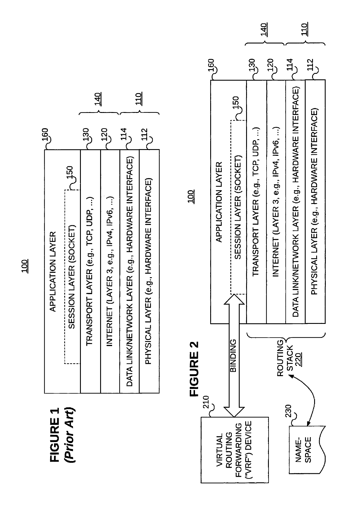
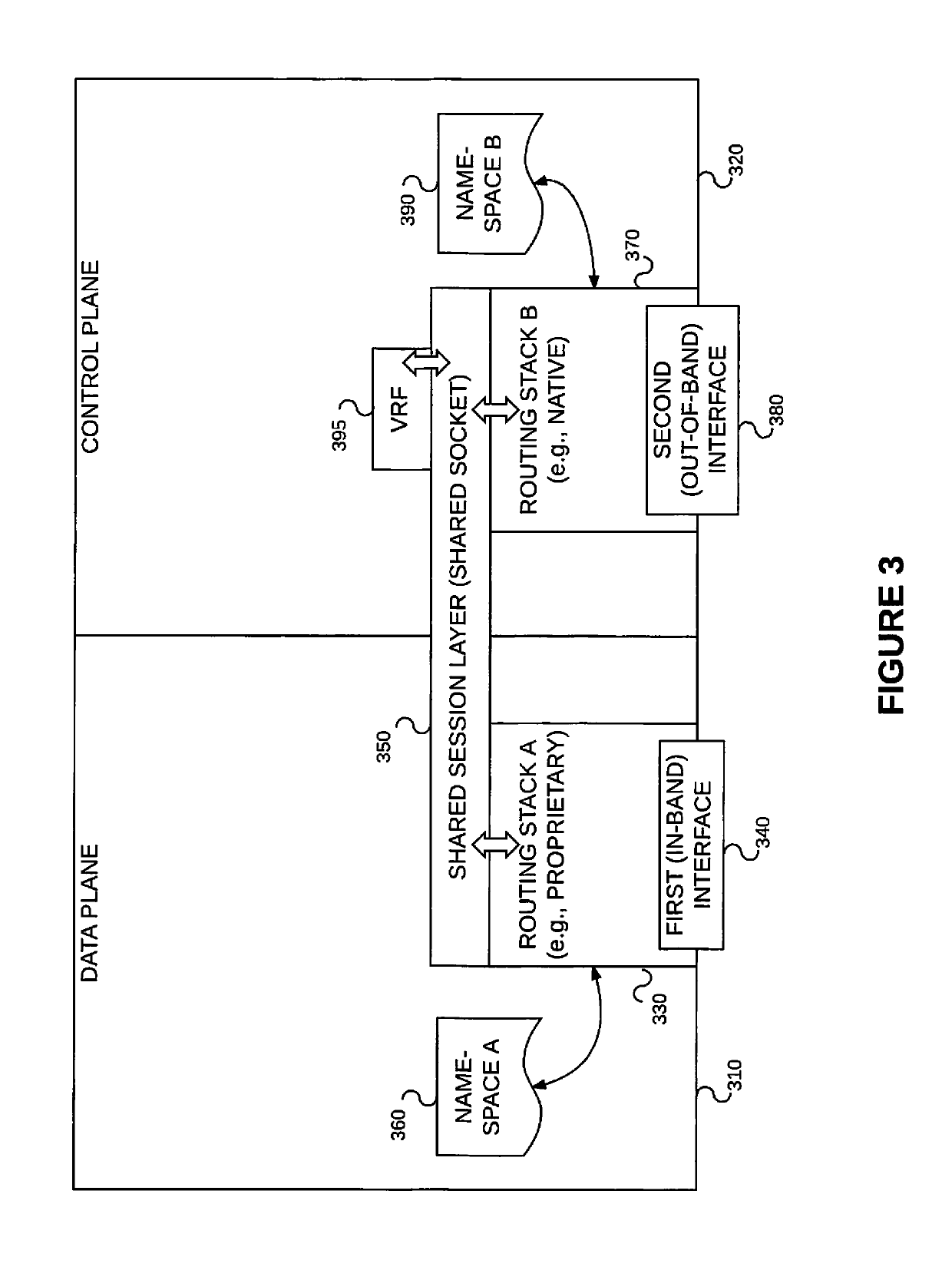
[0035]Example embodiments consistent with the present invention may be implemented on a data forwarding device such as the one described above reference to FIG. 3. That is, the data forwarding device may include (1) a first routing stack 330 associated with a first namespace 360 and a first (e.g., in-band data plane) interface 340, (2) a second routing stack 370 associated with a second namespace 390 and a second (e.g., out-of-band control plane) interface 380, wherein at least some forwarding information included in the second namespace 390 is incompatible with the first routing stack 330, (3) a VRF device or instance 395, and (4) a shared session layer socket 350 associated with the first routing stack 330 and the second routing stack 370 and bound to the VRF instance 395, wherein the VRF 395 is associated with the second (e.g., out-of-band control plane) interface 380 via the second routing stack 370. Some interfaces (e.g., in-band interfaces 340) are managed...


PUM


Abstract

The problem of processing an egress packet by a data forwarding device having (1) a first routing stack associated with a first namespace and a first interface, (2) a second routing stack associated with a second namespace and a second interface, wherein at least some forwarding information included in the second namespace is incompatible with the first routing stack, (3) a virtual routing and forwarding instance (VRF), and (4) a shared session layer socket associated with both the first and second routing stack, and bound to the VRF, where the VRF is associated with the second interface via the second routing stack, is solved by: adding the first interface to the VRF whereby the VRF is associated with both the first and second interfaces; and responsive to the adding of the first interface to the VRF, (1) adding routes from the second namespace to the first namespace such that network address prefixes of the second namespace are associated with a “special” next hop, and (2) flagging the shared session layer socket bound to the VRF. When an egress packet on the flagged shared session layer socket is received, the data forwarding device (1) sends the egress packet to the first routing stack for processing, (2) looks up next hop information using the first namespace of the first routing stack, and (3) determines whether or not the next hop information is a “special” next hop. Responsive to a determination that the next hop information is a “special” next hop, the data forwarding device injects the egress packet into the second routing stack for processing.

Description

§ 1 BACKGROUND OF THE INVENTION§ 1.1 Field of the Invention[0001]The present invention concerns network communications. More specifically, the present invention concerns processing packets in a routing instance that is distributed across at least two different routing stacks.§ 1.2 Background Information§ 1.2.1 TCP / IP Conceptual Model[0002]FIG. 1 illustrates a conceptual model 100 and set of communications protocols used on the Internet and similar computer networks. The conceptual model 100 is slightly modified from the model commonly referred to as the Internet protocol suite or TCP / IP. The conceptual model 100 provides end-to-end data communication specifying how data should be packetized, addressed, transmitted, routed, and received. This functionality is organized into abstraction layers which classify all related protocols according to the scope of networking involved. From lowest to highest, the abstraction layers include a physical layer 112, a data link or network layer 114,...

Claims


Application Information

Patent Timeline
Patent Type & Authority Patents(United States)
IPC IPC(8): H04L12/741H04L12/713H04L12/801H04L45/586H04L45/74
CPCH04L45/74H04L45/586H04L47/17
Inventor THOMAS, REJIRAMESH, VIVEKBHATTA, PRANAVADATTA DEVAKI NARASIMHA
Owner JUMIPER NETWORKS INC
Why Eureka
Try Eureka