Flow aid for infusion structure, infusion structure comprising a flow aid and method for infiltrating fibre material with resin

a flow aid and fibre material technology, applied in the field of flow aid for infusion structure, can solve the problems of large residual amount, large number of components, and large amount of resin, and achieve the effects of facilitating the flow inside the flow space, preventing gas cavities effectively, and facilitating the flow

Active Publication Date: 2019-10-29
AIRBUS DEFENCE & SPACE
View PDF24 Cites 0 Cited by
  • Summary
  • Abstract
  • Description
  • Claims
  • Application Information

AI Technical Summary

Benefits of technology

[0008]One idea of the present invention is to provide a device and a method by which fibre material can be infiltrated as uniformly as possible with resin to produce a fibre composite component, in particular without requiring a great amount of resin, and also as effectively and efficiently as possible.

Problems solved by technology

A disadvantage of this prior art is that an excess of resin is generally unavoidable.
A large amount of residual, unused resin material usually remains in the distributor media and / or on the fibre composite component to be produced.
A disadvantage of this prior art is that a large number of components is required and that adjusting the pressure difference requires a relatively large outlay in terms of apparatus and a relatively great control effort in terms of the process.

Method used


Image

  • Flow aid for infusion structure, infusion structure comprising a flow aid and method for infiltrating fibre material with resin
  • Flow aid for infusion structure, infusion structure comprising a flow aid and method for infiltrating fibre material with resin

Examples


Embodiment Construction

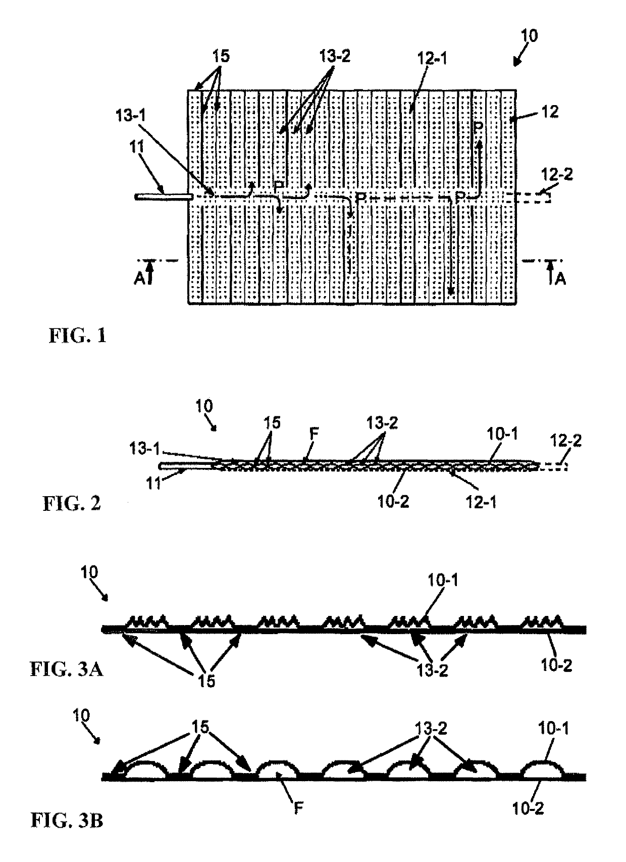
[0057]FIG. 1 shows a flow aid 10 comprising an inlet 11 for introducing resin, which inlet opens into a longitudinal channel 13-1 which leads to transverse channels 13-2 branching off therefrom. The transverse channels 13-2 are formed by connecting seams 15. An outlet 12 for discharging resin is formed by perforations 12-1 which are uniformly distributed over the entire flow aid 10. The flow aid 10 can optionally have one exit opening 12-2 (indicated by dashed lines) at which a differential pressure can be generated.

[0058]Resin flows from the inlet 11 through the longitudinal channel 13-1 and the transverse channels 13-2 along flow paths P to the perforations 12-1 and can flow out of the flow aid 10 via the perforations 12-1. The perforations 12-1 thus form an interface to a fibre material to be infiltrated or to a fibre composite component to be produced (not shown).

[0059]FIG. 2 is a schematic sectional view along the line A-A in FIG. 1 and shows an upper layer 10-1 and a lower lay...


PUM

PropertyMeasurementUnit
atmospheric pressureaaaaaaaaaa
diameteraaaaaaaaaa
diameteraaaaaaaaaa

Abstract

A flow aid for an infusion structure for infiltrating fiber material with resin to produce a fiber composite component includes a resin-impermeable upper layer and a lower layer which are joined together in a peripheral region of the flow aid and provide a flow space between the two layers. The lower layer provides an outlet for discharging resin out of the flow aid into an interior of the infusion structure. The flow aid includes an inlet for feeding the resin into the flow space, thereby facilitating uniform distribution of the resin over all of the fiber material.

Description

FIELD OF THE INVENTION[0001]The present invention relates to a flow aid for an infusion structure, to an infusion structure comprising a flow aid of this type and to a method for infiltrating fibre material with resin to produce a fibre composite component.BACKGROUND OF THE INVENTION[0002]To produce fibre composite components, moulds are often used into which fibre material which is to be infiltrated with resin is introduced. The fibre material is then covered, for example with a gas-tight sheath which can be sealed off from the mould, and resin is infiltrated in at least one place of the “infusion structure” thus formed, in that a vacuum is produced in the gas-tight sealed interior of the structure in at least one other place of the structure. This method known as the vacuum infusion technique is used, for example in the “Seaman composites resin infusion moulding” (SCRIMP) process, in the “vacuum assisted resin transfer moulding” (VARTM) process, in the “vacuum assisted resin injec...

Claims


Application Information

Patent Timeline
Patent Type & Authority Patents(United States)
IPC IPC(8): B29C70/44B29C70/54B29C70/48
CPCB29C70/547B29C70/48B29C70/548B29C70/44
Inventor FILSINGER, JUERGENSTEINHILBER, MICHAEL
Owner AIRBUS DEFENCE & SPACE
Why Eureka
Try Eureka