Anti-rollback wheelchair device

a wheelchair and anti-rolling technology, applied in the direction of freewheel clutches, clutches, ambulance services, etc., can solve the problems of serious safety issues, inability to propel rearward to control what is commonly called a “wheelie”, and jamming of components

Active Publication Date: 2019-11-12
GREEN STEPHEN
View PDF22 Cites 1 Cited by
  • Summary
  • Abstract
  • Description
  • Claims
  • Application Information

AI Technical Summary

Benefits of technology

[0010]The present invention furthers the state of the art by providing an anti-rollback mechanism for manual wheelchairs that allows both free-wheeling and anti-rollback modes, with the ability to shift between modes at any time, including while the wheelchair is on a ramp. Additionally, the invention incorporates an overload clutch mechanism that allows the manual wheelchair user (MWU) to propel the wheelchair backward, even while the mechanism is engaged in anti-rollback mode. The invention can be incorporated into the rear wheel hubs such that the appearance of the wheelchair is unchanged, an important aesthetic consideration for many MWU's. It can also be attached to a typical wheelchair parking brake lever, while retaining full functionality. The parking brake lever embodiment is attractive for those cases where the MWU prefers to keep the rear wheels of the wheelchair unchanged, and but still wants the advantages of the anti-rollback device.

Problems solved by technology

First among these is the inability to propel rearward to control what is commonly called a “wheelie”.
This is a serious safety issue.
In effect, the load on the mechanism that holds the wheelchair and MWU on the incline jams the components so that they cannot be disengaged, or changed in mode to free wheeling.
If the MWU has any challenges to strength or coordination, common among MWU's, this is a serious problem.
While this does allow changing from hill holding mode to freewheeling mode on a ramp, it is unsafe for the MWU to do so, as their hands will have been removed from the pushrims to grasp the levers.
While the MWU's hands are off of the pushrims, they do not have control of the wheelchair position or movement.
Consequently, moving the toggle mechanism lever to disengage the hill holder results in the chair rolling backwards on the incline in an uncontrolled manner until the MWU can re-grasp the pushrims to control the wheelchair.
As many MWU's have impaired strength and coordination, this situation is unacceptably dangerous.
The MagicWheels two-speed geared wheels include clutches in their hypocycloidal drive which do not allow the wheels to roll backward when the low speed mode is being used.
They also can be over-ridden by extra force being applied rearward on the pushrim.
The major disadvantages of the units are their heavy weight and high cost.
Additionally they cannot be shifted from hill holding mode to freewheeling while on an incline.
Like other inventions, these devices do not allow rearward propulsion for control of wheelies, and they cannot be shifted from anti-rollback to freewheeling while the wheelchair is on an incline.
Various roller clutch mechanisms are known to the art, but fail to adequately address wheelchair anti-rollback needs.
This type of clutch is complex and problematically expensive to manufacture in small quantities for wheelchair applications.
Due to the dependence on individual springs for roller biasing, the arrangement thus taught is limited to a bi-state operation, as the springs will push the rollers either one direction on the other, and are not intended or able to achieve an intermediate position.
This lack of a free-wheeling functionality makes this mechanism unacceptable for a wheelchair anti-rollback application.
This arrangement as presented is of greater complexity and cost than is needed for wheelchair transmissions.

Method used


Image

  • Anti-rollback wheelchair device
  • Anti-rollback wheelchair device
  • Anti-rollback wheelchair device

Examples


Embodiment Construction

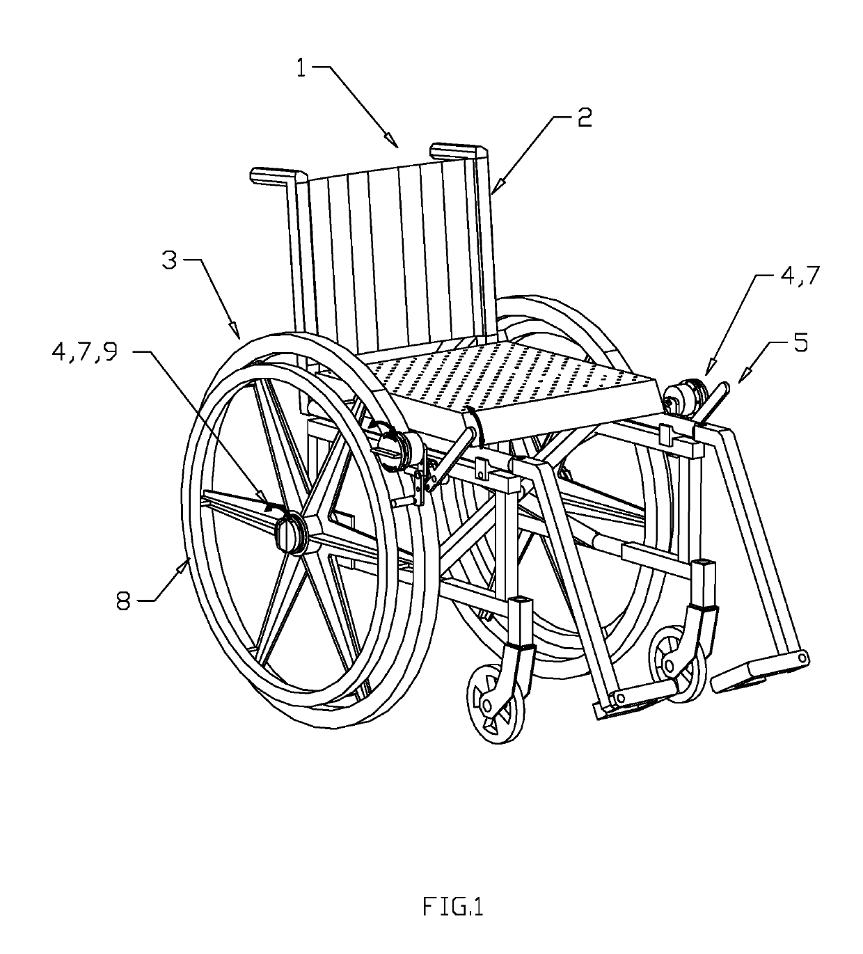
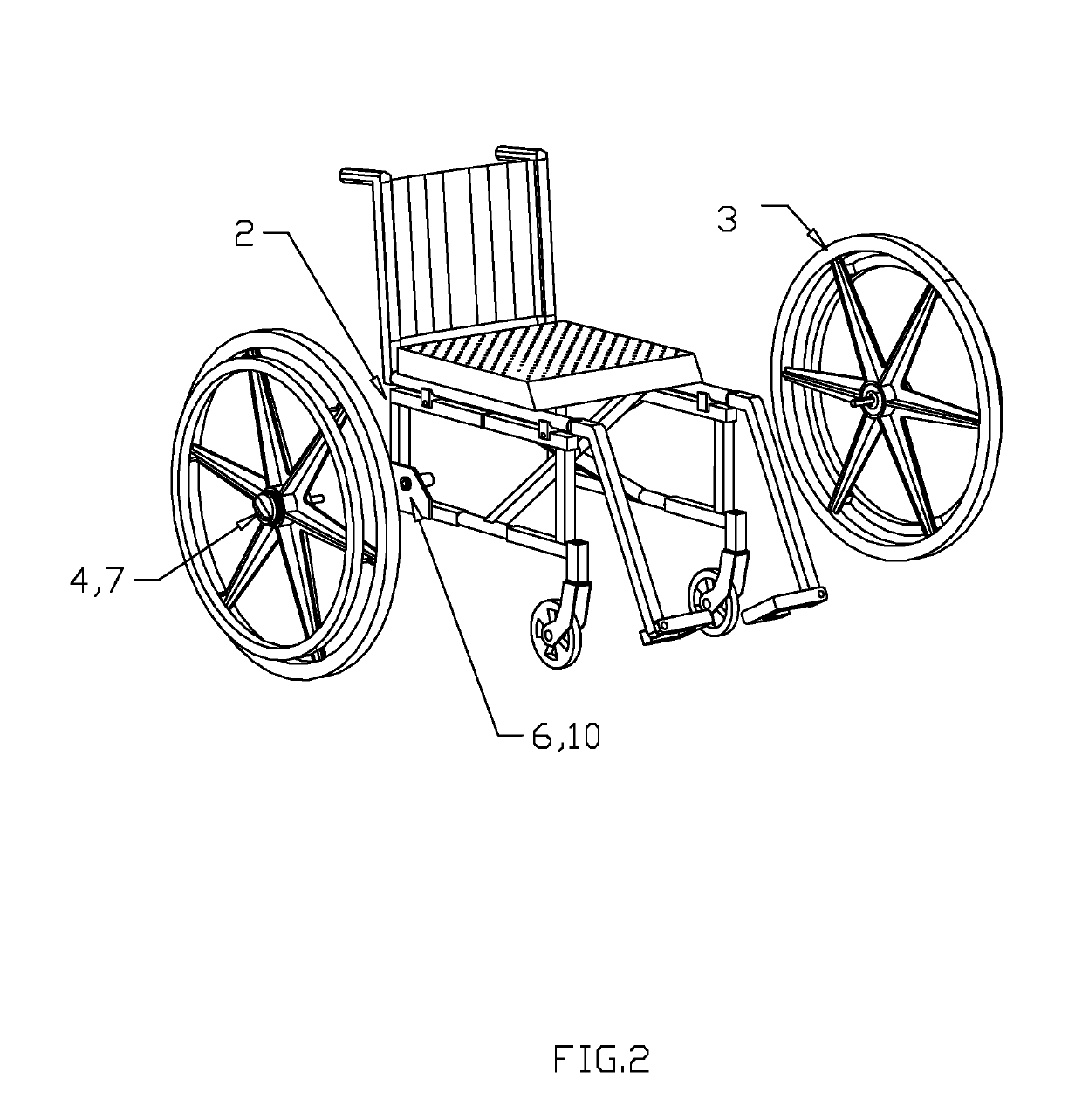
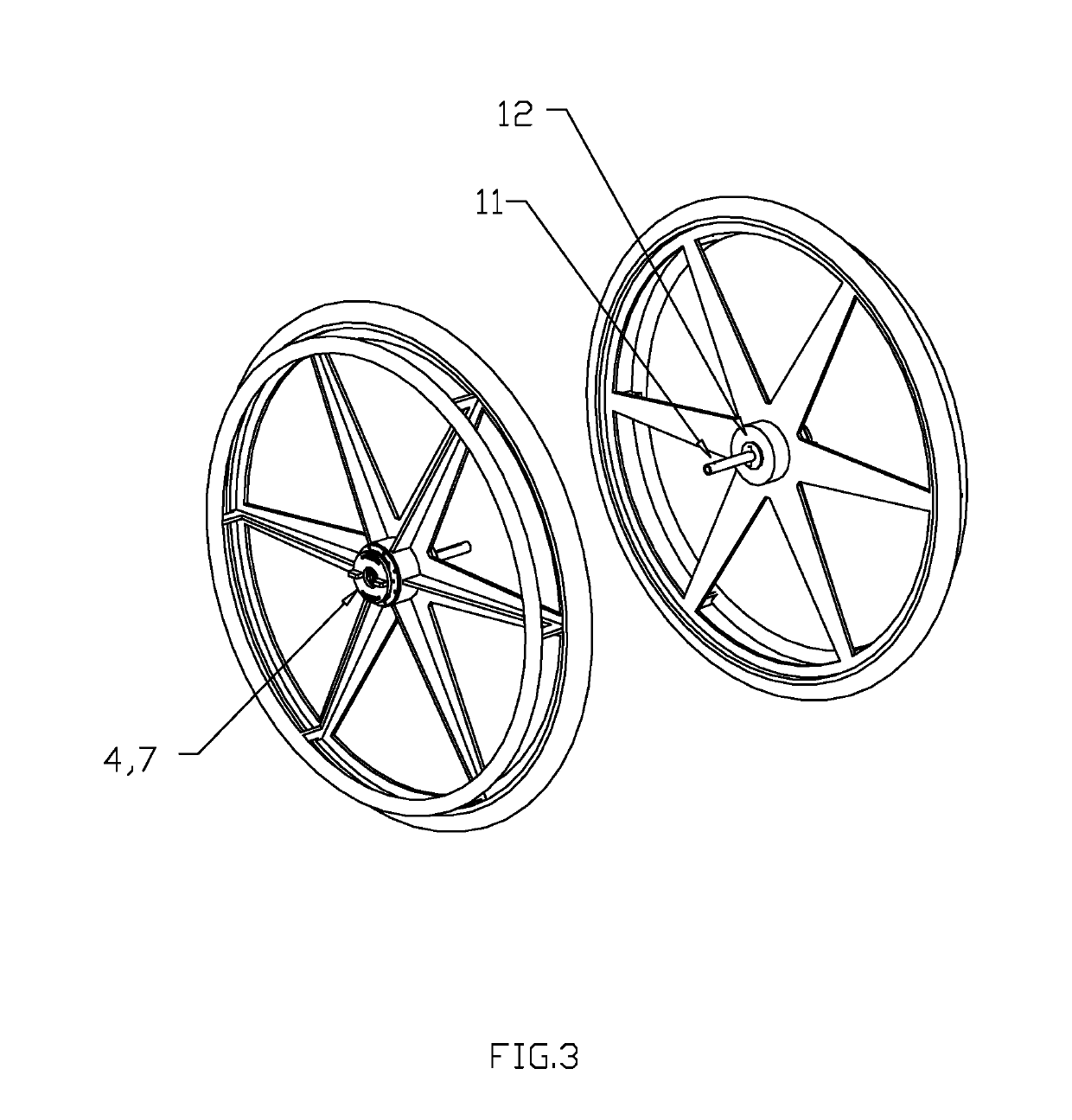
[0030]With reference to FIG. 1, a typical manual wheelchair 1 is shown with two of the preferred embodiments of the wheelchair anti-rollback device invention installed on a typical manual wheelchair frame 2. Although both embodiments are shown on a single wheelchair in the interest of brevity and clarity, a typical installation would include only one embodiment. Either embodiment of this invention will provide the functionality of two modes of operation, free-wheeling and anti-rollback. Rear wheels 3 with typical fixed pushrims 8 are shown in place on wheelchair frame 2. Mode selector knob 7 can be seen with knob rotation arrow 9 showing the knob rotation required to change modes. Obscured by knob 7 is the anti-rollback hub 4. Hub spindle socket 6 with torque reaction slot 10 is shown in FIGS. 2 and 4. Spindle shaft 11 with spindle shaft torque reaction pin 12 is shown in FIG. 3. The embodiment of this invention as appropriate to mount in a wheelchair wheel is shown in FIG. 5 along ...


PUM


Abstract

A wheelchair anti-rollback device utilizes one-way roller clutches which incorporate a selectable free-rotation functionality such that the wheelchair user can select between anti-rollback and free-wheeling modes. The anti-rollback mode is of utility when the wheelchair user is propelling up ramps. The modal selection is by means of a knob positioned on the centerline rotation axis of the mechanism. The mechanism also included functionality that allows mode change from anti-rollback to free-wheeling to be made at any time, including while the chair is on an inclined ramp. The invention can incorporated into the hub of the rear wheels of a wheelchair or into the toggle mechanism of typically used to actuate parking brakes. When incorporated into a wheelchair, the invention gives the wheelchair user greater control and ease in ascending ramps.

Description

BACKGROUND OF THE INVENTION[0001]The need for a mechanism that will restrain a wheelchair from rolling backwards has been recognized as long as wheelchairs have been constructed. One of the uses for such a device is to prevent a user's wheelchair from rolling backward away from them as they sit down in the wheelchair, or as they stand up. These are often called anti-rollback devices. Another need arises from the challenges in ascending inclines and ramps with a manual drive wheelchair. In this instance the manual wheelchair user (MWU) must provide the propelling force to overcome the gravitational load. In common practice the MWU uses pushrims to rotate the rear wheel a fraction of a revolution, typically about 30 to 45 degrees. At the end of the push stroke the user must maintain a force through the pushrims to keep the chair from rolling backward. If another push stroke is required while on the incline, the MWU must let go of the pushrims, move their hands to a new placement on th...

Claims


Application Information

Patent Timeline
Patent Type & Authority Patents(United States)
IPC IPC(8): A61G5/02F16D43/204F16D41/06A61G5/10
CPCA61G5/101A61G5/1016F16D43/204F16D41/06A61G5/1035A61G5/1018A61G5/1086
Inventor GREEN, STEPHEN
Owner GREEN STEPHEN
Why Eureka
Try Eureka