Apparatus, systems and method for oil and gas operations

a technology for oil and gas operations and apparatus, applied in the direction of fluid removal, sealing/packing, borehole/well accessories, etc., can solve the problems of compromising the original design of the christmas tree, complex and carefully designed christmas tree equipment, and avoiding deviations in the location of critical components

Active Publication Date: 2019-11-19
ENPRO SUBSEA
View PDF70 Cites 5 Cited by
  • Summary
  • Abstract
  • Description
  • Claims
  • Application Information

AI Technical Summary

Benefits of technology

[0003]There are a number of reasons why it is desirable to access a flow system in an oil and gas production system. In the context of this specification, the term “fluid intervention” is used to encapsulate any method which accesses a flow line, manifold or tubing in an oil and gas production, injection or transportation system. This includes (but is not limited to) accessing a flow system for fluid sampling, fluid diversion, fluid recovery, fluid injection, fluid circulation, fluid measurement and / or fluid metering. This can be distinguished from full well intervention operations, which generally provide full (or near full) access to the wellbore. Full well intervention processes and applications are often technically complex, time-consuming and have a different cost profile to fluid intervention operations. It will be apparent from the following description that the present invention has application to full well intervention operations. However, it is an advantage of the invention that full well intervention may be avoided, and therefore preferred embodiments of the invention provide methods and apparatus for fluid intervention which do not require full well intervention processes.
[0004]International patent application numbers WO00 / 70185, WO2005 / 047646, and WO2005 / 083228 describe a number of configurations for accessing a hydrocarbon well via a choke body on a Christmas tree.
[0005]Although a choke body provides a convenient access point in some applications, the methods of WO00 / 70185, WO2005 / 047646, and WO2005 / 083228 do have a number of disadvantages. Firstly, a Christmas tree is a complex and carefully-designed piece of equipment. The choke performs an important function in production or injection processes, and its location on the Christmas tree is selected to be optimal for its intended operation. Where the choke is removed from the choke body, as proposed in the prior art, the choke must be repositioned elsewhere in the flow system to maintain its functionality. This compromises the original design of the Christmas tree, as it requires the choke to be located in a sub-optimal position.
[0006]Secondly, a choke body on a Christmas tree is typically not designed to support dynamic and / or static loads imparted by intervention equipment and processes. Typical loads on a choke body in normal use would be of the order of 0.5 to 1 tonnes, and the Christmas tree is engineered with this in mind. In comparison, a typical flow metering system as contemplated in the prior art may have a weight of the order of 2 to 3 tonnes, and the dynamic loads may be more than three times that value. Mounting a metering system (or other fluid intervention equipment) on the choke body therefore exposes that part of the Christmas tree to loads in excess of those that it is designed to withstand, creating a risk of damage to the structure. This problem may be exacerbated in deepwater applications, where even greater loads may be experienced due to thicker and / or stiffer components used in the subsea infrastructure.
[0007]In addition to the load restrictions identified above, positioning the flow intervention equipment on the choke body may limit the access available to large items of process equipment and / or access of divers or remotely operated vehicles (ROVs) to the process equipment or other parts of the tree.
[0008]Furthermore, modifying the Christmas tree so that the chokes are in non-standard positions is generally undesirable. It is preferable for divers and / or ROV operators to be completely familiar with the configuration of components on the Christmas tree, and deviations in the location of critical components are preferably avoided.

Problems solved by technology

Full well intervention processes and applications are often technically complex, time-consuming and have a different cost profile to fluid intervention operations.
Firstly, a Christmas tree is a complex and carefully-designed piece of equipment.
This compromises the original design of the Christmas tree, as it requires the choke to be located in a sub-optimal position.
Secondly, a choke body on a Christmas tree is typically not designed to support dynamic and / or static loads imparted by intervention equipment and processes.
Mounting a metering system (or other fluid intervention equipment) on the choke body therefore exposes that part of the Christmas tree to loads in excess of those that it is designed to withstand, creating a risk of damage to the structure.
This problem may be exacerbated in deepwater applications, where even greater loads may be experienced due to thicker and / or stiffer components used in the subsea infrastructure.
In addition to the load restrictions identified above, positioning the flow intervention equipment on the choke body may limit the access available to large items of process equipment and / or access of divers or remotely operated vehicles (ROVs) to the process equipment or other parts of the tree.
Furthermore, modifying the Christmas tree so that the chokes are in non-standard positions is generally undesirable.
Another drawback of the prior art proposals is that not all Christmas trees have chokes integrated with the system; approaches which rely on Christmas tree choke body access to the flow system are not applicable to these types of tree.

Method used


Image

  • Apparatus, systems and method for oil and gas operations
  • Apparatus, systems and method for oil and gas operations
  • Apparatus, systems and method for oil and gas operations

Examples


Embodiment Construction

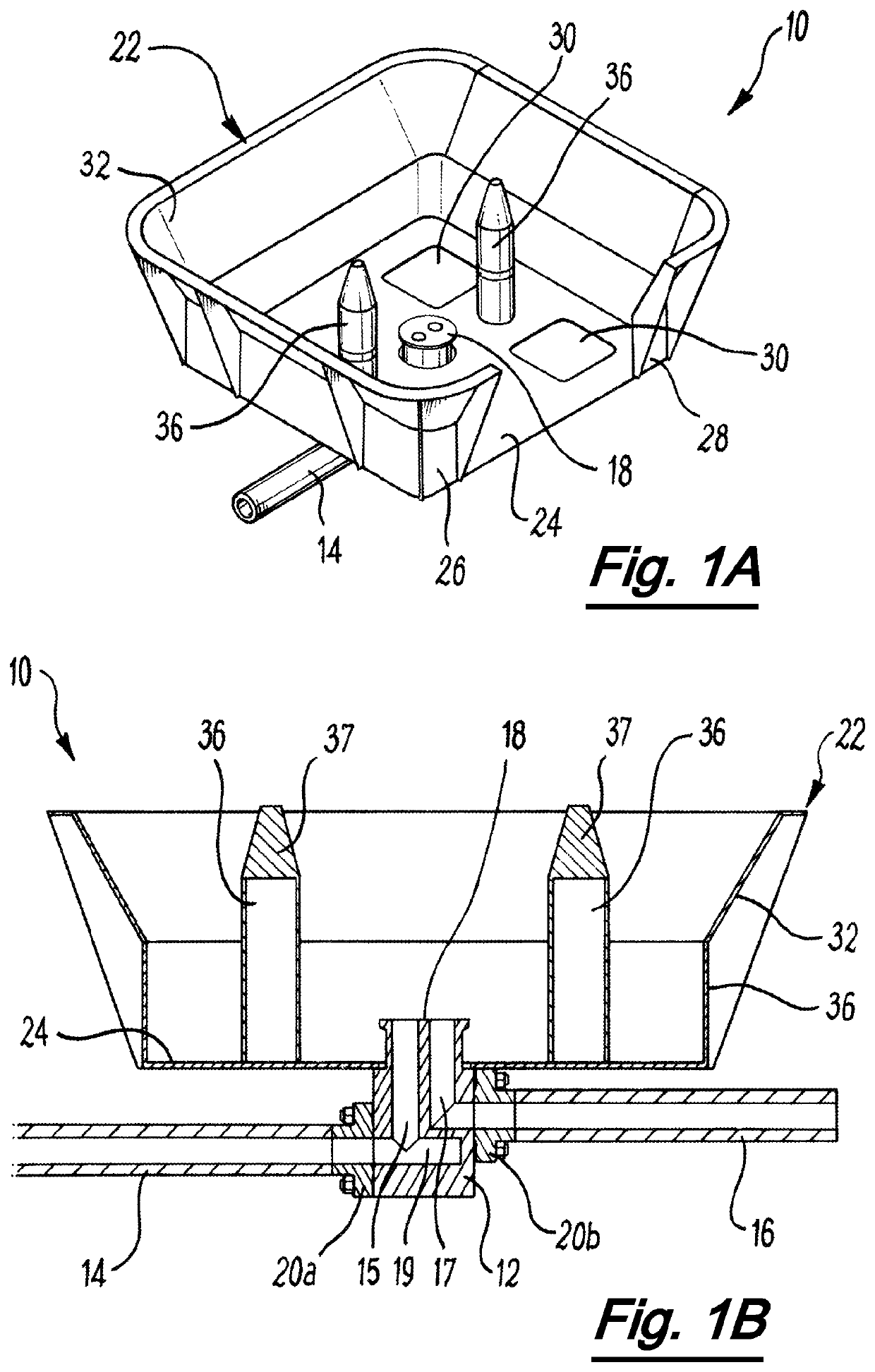
[0079]Referring firstly to FIGS. 1A and 1B, there is shown in isometric and sectional views a flow access apparatus according to a first embodiment of the invention. The flow access apparatus, generally depicted at 10, is designed to provide access to a flow system which forms part of a subsea hydrocarbon production system or installation. The flow access apparatus comprises a body 12, which is shown connected to first and second flow lines 14 and 16. In this embodiment, the connection between the first and second flow lines 14 and 16 and the body 12 is made up by flange connectors 20a, 20b. In this example, first flow line 14 receives production fluid from a subsea tree (not shown) and second flow line 16 is connected to a subsea manifold or end termination.

[0080]The body defines a flow access interface, generally shown at 18, which in this embodiment is upward facing and arranged substantially vertically. The apparatus of this embodiment is configured as a dual bore hub, which is ...


PUM


Abstract

The invention provides an apparatus and system for accessing a flow system (such as a subsea tree) in a subsea oil and gas production installation, and method of use. The apparatus comprises a body and a plurality of connectors configured to connect the apparatus to the flow system. A flow access interface is provided on the body for connecting the apparatus to a subsea process apparatus, and the body defines a plurality of flow paths. Each flow path fluidly connects one of the plurality of connectors to the flow access interface to provide an intervention path from a connected subsea process apparatus to the flow system in use. Aspects of the invention have particular application to flow metering, fluid sampling, and well scale squeeze operations.

Description

[0001]The present invention relates to apparatus, systems and methods for oil and gas operations, in particular to apparatus, systems and methods for fluid intervention in oil and gas production or injection systems. The invention has particular application to subsea oil and gas operations, and aspects of the invention relate specifically to apparatus, systems and methods for fluid intervention in subsea oil and gas production and injection infrastructure.BACKGROUND TO THE INVENTION[0002]In the field of oil and gas exploration and production, it is common to install an assembly of valves, spools and fittings on a wellhead for the control of fluid flow into or out of the well. A Christmas tree is a type of fluid manifold used in the oil and gas industry in surface well and subsea well configurations and have a wide range of functions, including chemical injection, well intervention, pressure relief and well monitoring. Christmas trees are also used to control the injection of water o...

Claims


Application Information

Patent Timeline
Patent Type & Authority Patents(United States)
IPC IPC(8): E21B33/035E21B33/038E21B33/076E21B37/06E21B43/01E21B49/08
CPCE21B33/076E21B33/035E21B33/038E21B37/06E21B49/08E21B43/01E21B43/013
Inventor DONALD, IANREID, JOHN
Owner ENPRO SUBSEA
Why Eureka
Try Eureka