
Double stator permanent magnet machine with magnetic flux regulation

a permanent magnet machine and magnetic flux technology, applied in the direction of dynamo-electric converter control, dynamo-electric gear control, electric generator control, etc., can solve the problem of limiting the utilization of pm brushless machines in applications, limiting the use of variable-speed motors for selected applications, and limiting the use of pm brushless machines as variable-speed motors, etc., to achieve high reluctance

Active Publication Date: 2019-11-19
HAMILTON SUNDSTRAND CORP
View PDF23 Cites 0 Cited by
  • Summary
  • Abstract
  • Description
  • Claims
  • Application Information

AI Technical Summary

Benefits of technology

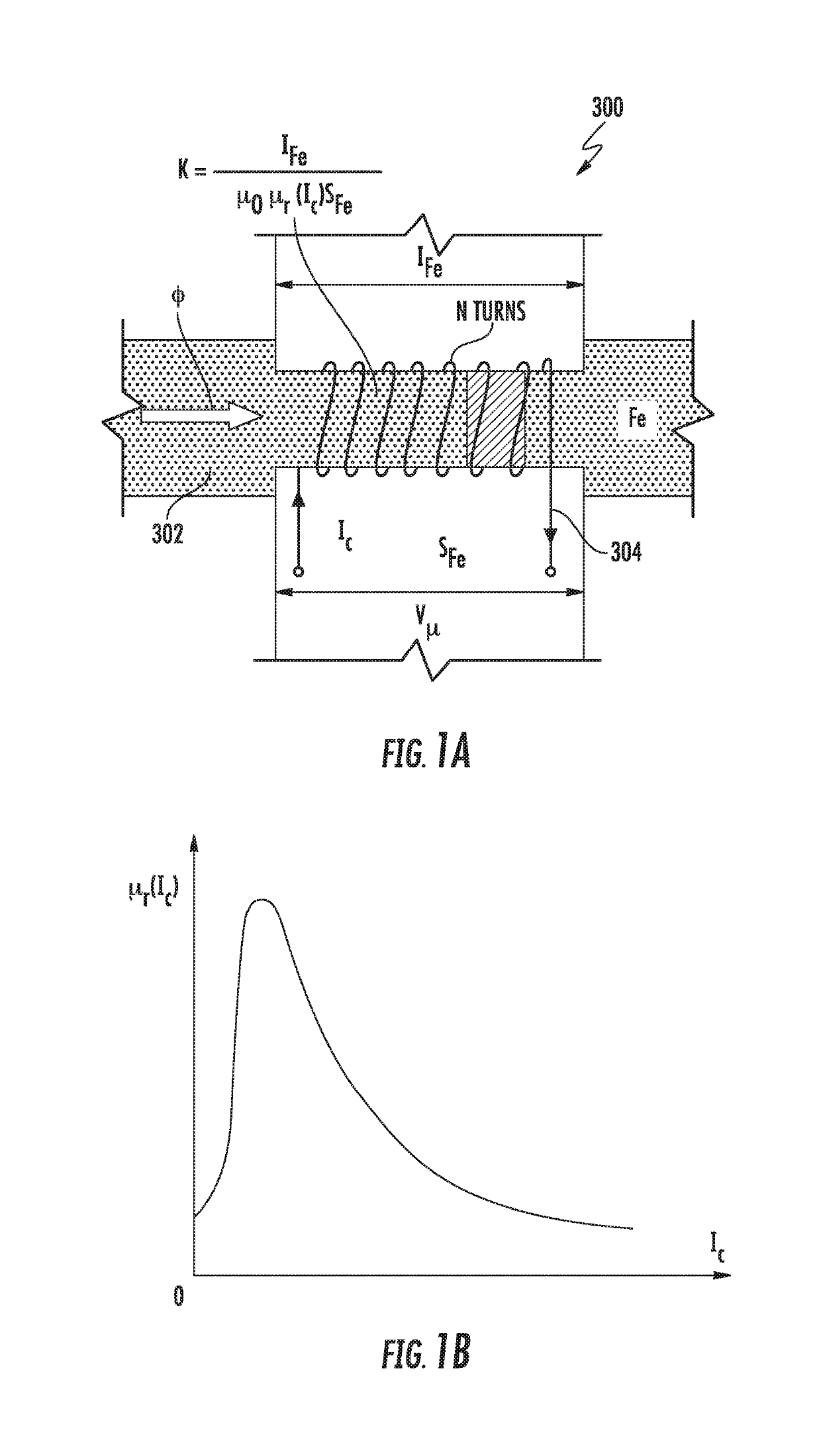
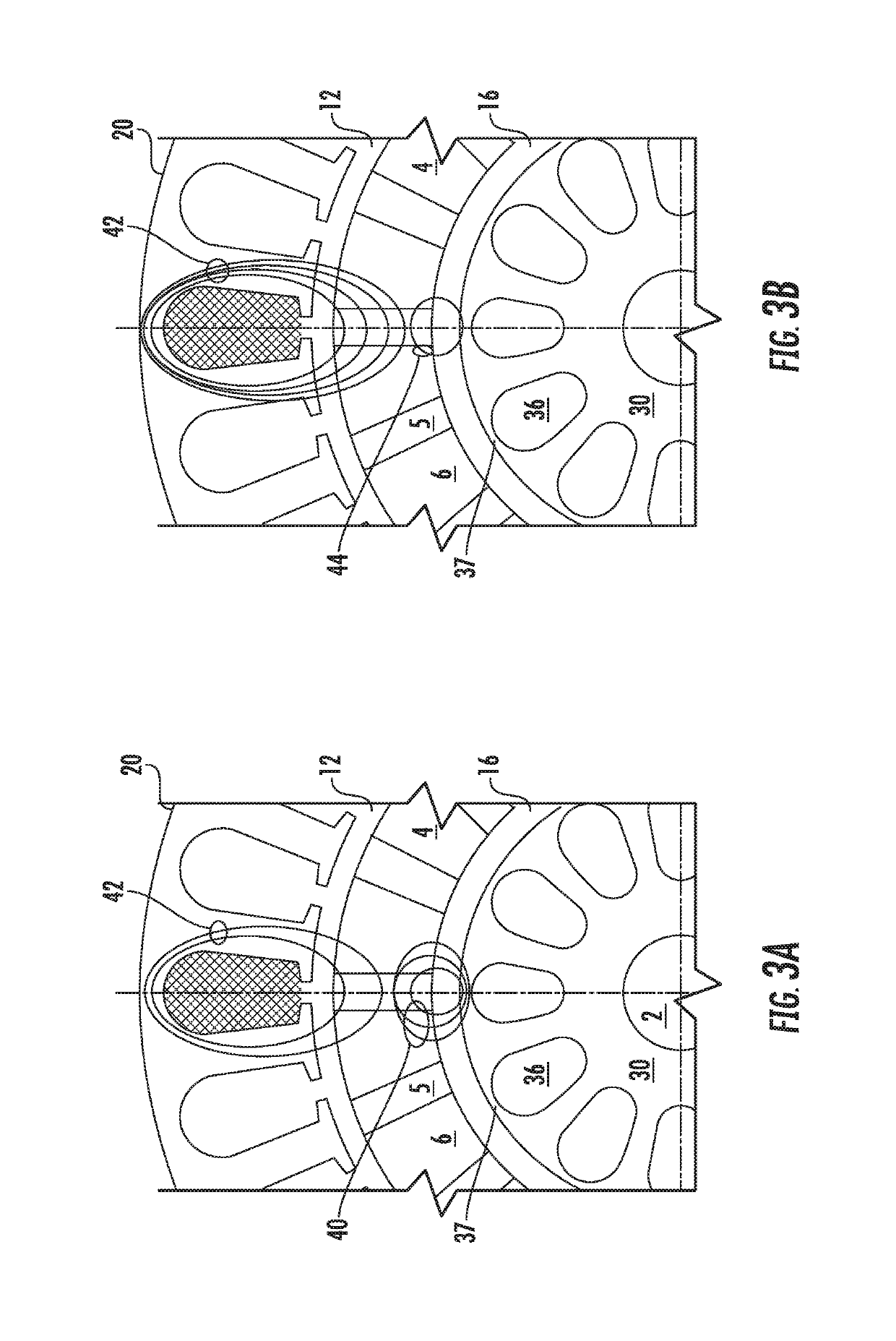
[0006]In addition to one or more of the features described above, or as an alternative, further embodiments may include that application of a control current Ic to the control coil at least partially magnetically saturates the saturable region for the second plurality of stator teeth to reduce shunting of air gap magnetic flux Φg, thereby controlling magnetic flux linkage ΨM between the PMs and the first plurality of stator coils
[0015]In addition to one or more of the features described above, or as an alternative, further embodiments may include that each saturable region between stator teeth of the inner stator assembly exhibits high reluctance when saturated limiting magnetic flux linkage from the PMs.

Problems solved by technology

As a result, constant magnetic flux requirements may limit utilization of PM brushless machines in applications as generators when the prime mover speed is variable, e.g., aircraft generators.
In addition, the constant magnetic flux also limits their utilization as variable-speed motors for selected applications, e.g., electric or hybrid-electric vehicle.
Control of magnetic excitation flux is not available in standard PM brushless dynamoelectric machines.
Such control has previously only been practical with current vector control techniques.
However, such d-axis current injection to control magnetic flux excitation has certain drawbacks, such as a significant increase in stator winding losses that can result in excess heat dissipated in the stator winding and irreversible demagnetization of low energy density rotor PMs, such as rotor PMs of the ferrite type.
This results in reduced weight, cost, and complexity of an electrical power generation system.
However, traditional PM machines have no convenient means to alter magnetic flux for regulating their output.

Method used


Image

  • Double stator permanent magnet machine with magnetic flux regulation
  • Double stator permanent magnet machine with magnetic flux regulation
  • Double stator permanent magnet machine with magnetic flux regulation

Examples


Embodiment Construction

[0035]For the purposes of promoting an understanding of the principles of the present disclosure, reference will now be made to the embodiments illustrated in the drawings, and specific language will be used to describe the same. It will nevertheless be understood that no limitation of the scope of this disclosure is thereby intended. The following description is merely illustrative in nature and is not intended to limit the present disclosure, its application or uses. It should be understood that throughout the drawings, corresponding reference numerals indicate like or corresponding parts and features. As used herein, the term controller refers to processing circuitry that may include an application specific integrated circuit (ASIC), an electronic circuit, an electronic processor (shared, dedicated, or group) and memory that executes one or more software or firmware programs, a combinational logic circuit, and / or other suitable interfaces and components that provide the described...


PUM


Abstract

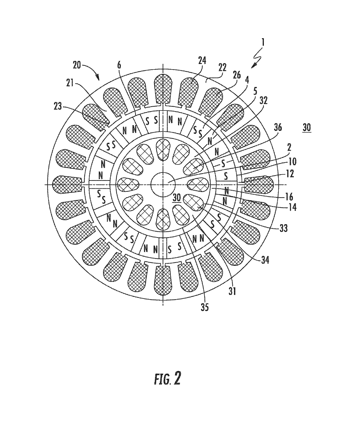
Embodiments herein relate to a permanent magnet (PM) dynamoelectric machine. The machine includes a drive shaft, a PM rotor assembly with multiple PMs arranged around a periphery of the rotor assembly, a first stator assembly including a stator yoke, having stator teeth mounted to the stator core with distal ends proximate the outer periphery of the rotor assembly separated by a first air gap and multiple stator coils mounted between the stator teeth. The machine also includes a second stator assembly including a stator yoke, having stator teeth mounted to the stator core with distal ends forming closed slots, proximate an inner periphery of the rotor assembly separated by a second air gap and at least one control coil, the a control coil wrapped about a saturable region of the stator teeth thereof, each saturable region is operable to divert magnetic flux of the PMs through the stator teeth.

Description

TECHNICAL FIELD[0001]The invention relates to permanent magnet (PM) dynamoelectric machines, and more particularly to PIM dynamoelectric machines with variable magnetic flux excitation.BACKGROUND[0002]Permanent magnet (PM) brushless dynamoelectric machines have the highest power density in comparison with all other classical electrical machines. They also have very high efficiency and good dynamic performance. On the other hand PM brushless machines exhibit constant magnetic flux which, conventionally mandates use of an external solid state converter to maintain control. As a result, constant magnetic flux requirements may limit utilization of PM brushless machines in applications as generators when the prime mover speed is variable, e.g., aircraft generators. In addition, the constant magnetic flux also limits their utilization as variable-speed motors for selected applications, e.g., electric or hybrid-electric vehicle.[0003]Control of magnetic excitation flux is not available in ...

Claims


Application Information

Patent Timeline
Patent Type & Authority Patents(United States)
IPC IPC(8): H02P9/32H02K21/04H02K21/12H02P9/30H02K16/04H02P21/06
CPCH02K21/12H02K21/046H02P21/06H02P9/32H02K16/04H02P9/302
Inventor GIERAS, JACEK F.
Owner HAMILTON SUNDSTRAND CORP
Learn More