Remotely operated aerial vehicle with reduced cross-section area during forward flight

a technology of forward flight and remote operation, which is applied in the direction of remote controlled aircraft, unmanned aerial vehicles, power plant construction, etc., can solve the problems of pilots unable to provide images and/or video back to operators, pilots unable to disrupt autonomous flight, and remote operators can assume control of remotely operated aerial vehicles. , to achieve the effect of reducing the cross-sectional area of the fram

Active Publication Date: 2019-11-26
EL-SIGHT LTD
View PDF4 Cites 0 Cited by
  • Summary
  • Abstract
  • Description
  • Claims
  • Application Information

AI Technical Summary

Benefits of technology

[0007]Each fixed rotor in the plurality of fixed rotors is mounted to a corresponding motor from among the plurality of motors. The corresponding motor controls the rotation of the fixed rotor. Each of the plurality of fixed rotors is mounted at a specified angle relative to the top and bottom surfaces. Mounting the fixed rotors at the specified angle minimizes the cross-sectional area of the frame when the remotely operated aerial vehicle flies in the specified forward direction.

Problems solved by technology

These UAVs may or may not provide images and / or video back to the operator.
When appropriate (e.g., due to component failures, weather conditions, etc.), the pilot can disrupt autonomous flight and assume control of the Remotely Operated Aerial Vehicle.

Method used


Image

  • Remotely operated aerial vehicle with reduced cross-section area during forward flight
  • Remotely operated aerial vehicle with reduced cross-section area during forward flight
  • Remotely operated aerial vehicle with reduced cross-section area during forward flight

Examples


Embodiment Construction

[0016]The present invention extends to methods, systems, devices, and apparatus, for remotely operated aerial vehicles with reduced cross-section area during forward flight. In one aspect, a remotely operated aerial vehicle is a rotor based Unmanned Aerial Vehicle (UAV) having a plurality of rotors. The remotely operated aerial vehicle includes a frame, a power source, a plurality of motors, and a corresponding plurality of fixed rotors.

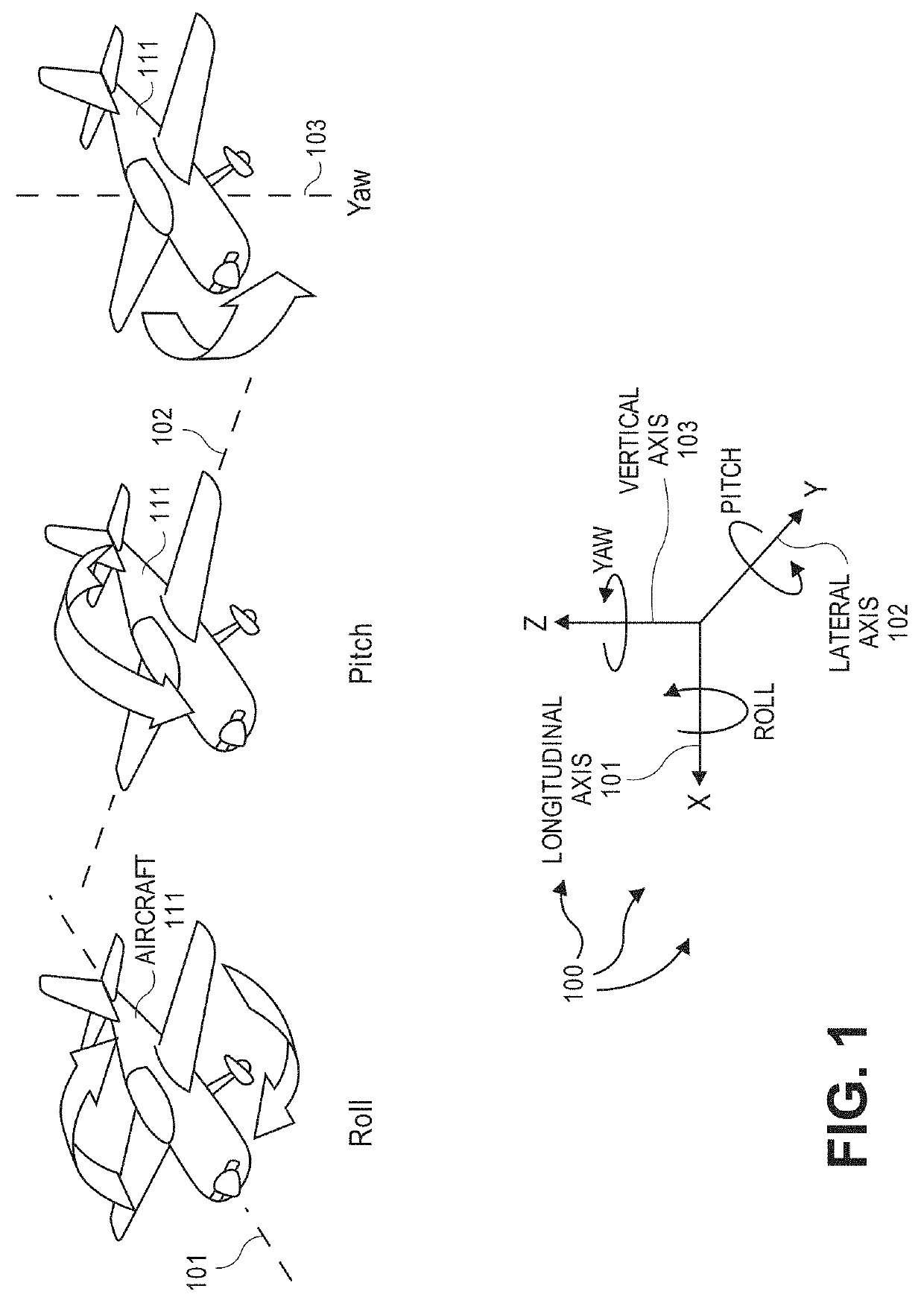
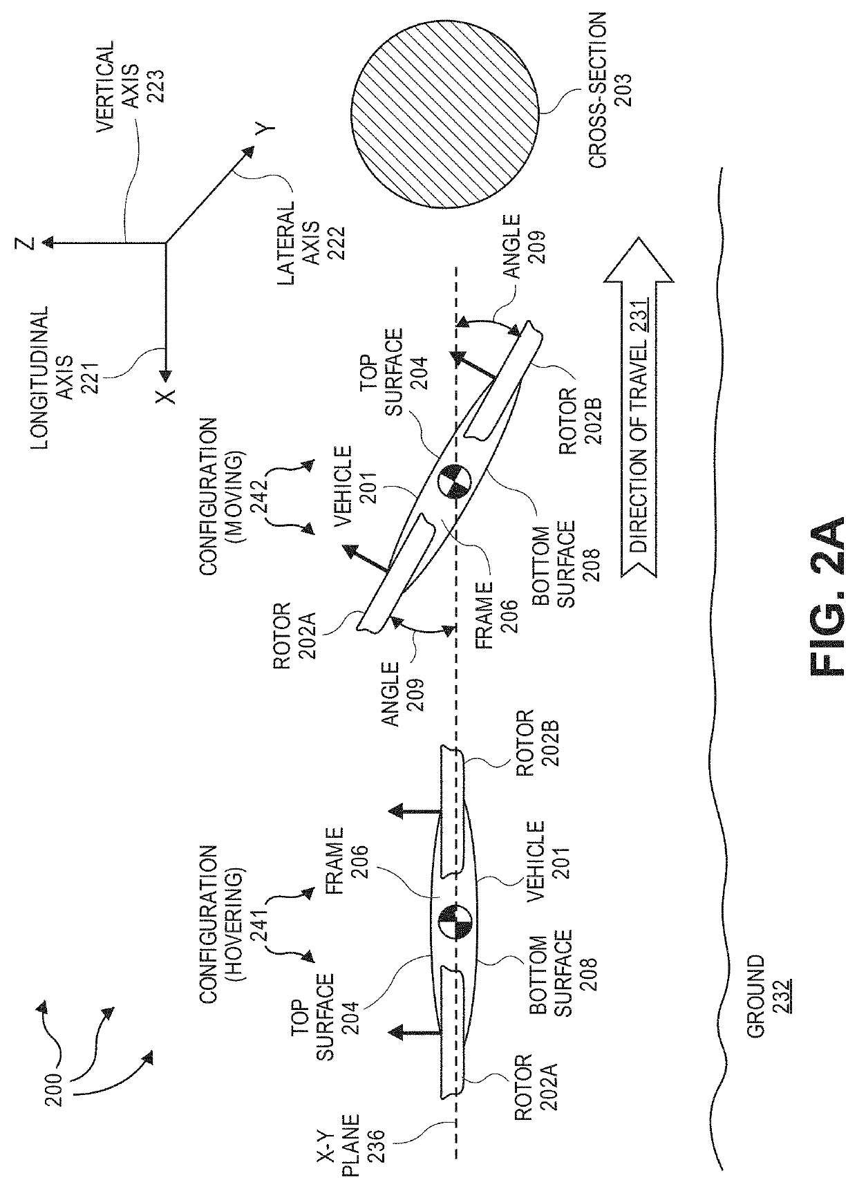
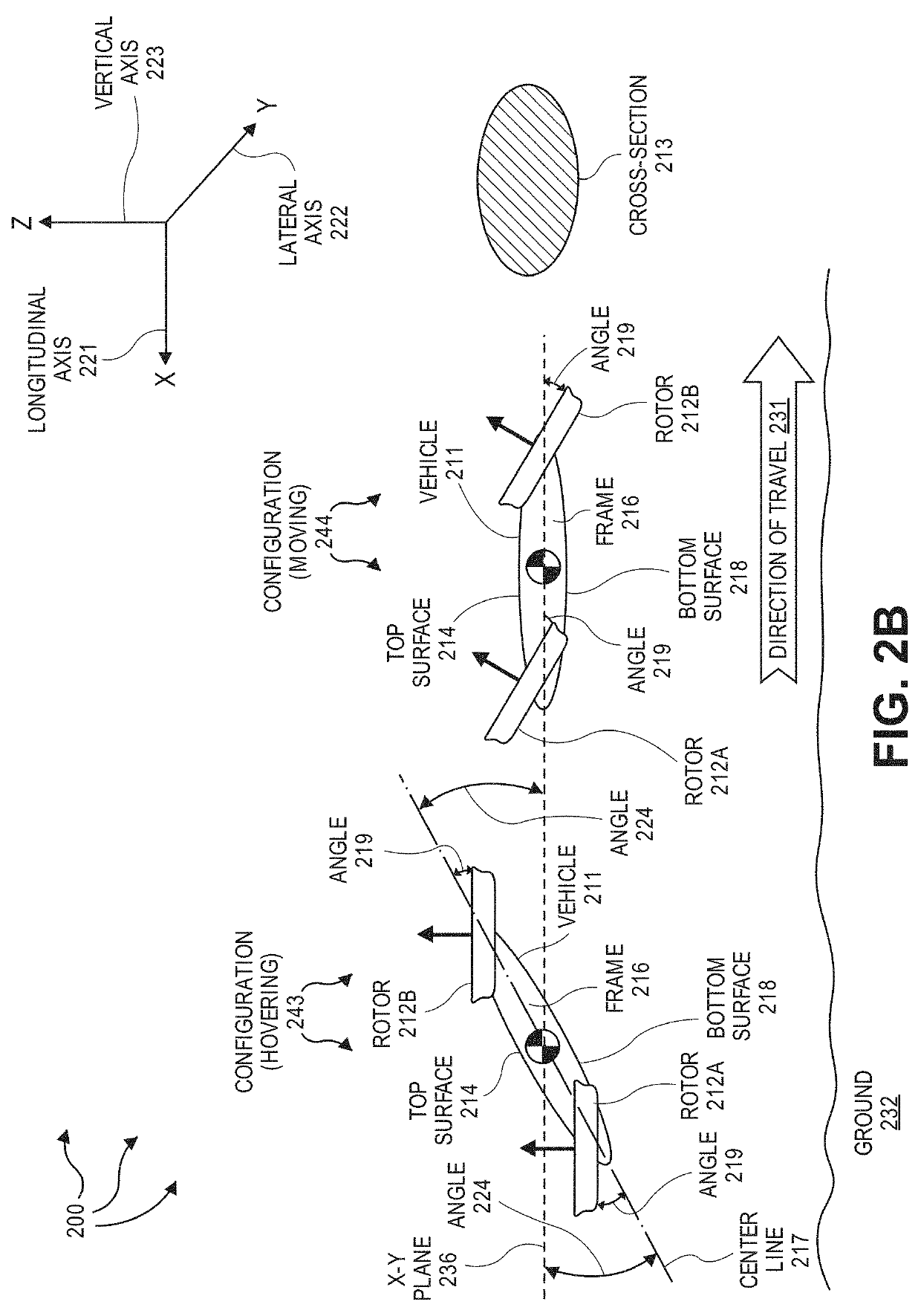
[0017]The frame also includes a top surface and a bottom surface that are essentially parallel to the ground when the remotely operated aerial vehicle flies in a specified forward direction. The power source is contained within the frame. Each of the plurality of motors are mounted to the frame and are powered by the power source.

[0018]Each fixed rotor in the plurality of fixed rotors is mounted to a corresponding motor from among the plurality of motors. The corresponding motor controls the rotation of the fixed rotor. Each of the plurality of fixed...


PUM


Abstract

The present invention extends to methods, systems, devices, and apparatus for remotely operated aerial vehicle with reduced cross-section area during forward flight. In one aspect, a remotely operated aerial vehicle is a rotor based Unmanned Aerial Vehicle (UAV) having a plurality of rotors. A remotely operated aerial vehicle includes a frame, a power source, a plurality of motors, and a corresponding plurality of fixed rotors. The frame includes a top surface. Each fixed rotor in the plurality of fixed rotors is mounted to a corresponding motor from among the plurality of motors. The corresponding motor controls the rotation of the fixed rotor. Each of the plurality of fixed rotors is mounted at a specified angle relative to the top surface. Mounting the fixed rotors at the specified angle minimizes the cross-sectional area of the frame when the remotely operated aerial vehicle flies in a specified direction.

Description

CROSS-REFERENCE TO RELATED APPLICATIONS[0001]This application claims the benefit of and priority to U.S. Provisional Patent Application Ser. No. 62 / 320,715 entitled “Remotely Operated Aerial Vehicles With Reduced Cross-Section Area During Forward Flight”, filed Apr. 11, 2016 by Paul E. I. Pounds, the entire contents of which are expressly incorporated by reference.BACKGROUNDBackground and Relevant Art[0002]The number of remotely operated (e.g., piloted) aerial vehicles, including unmanned aerial vehicles (UAVs), being flown continues to increase. A variety of different entities including hobbyists, delivery companies, intelligence agencies, surveyors, power companies, etc. use Remotely Operated Aerial Vehicles. Some Remotely Operated Aerial Vehicles operate past line of sight. On an ongoing basis and / or at a destination, the Remotely Operated Aerial Vehicle provides images and / or video of its surroundings back to a monitoring system (which may or may not be the location of the opera...

Claims


Application Information

Patent Timeline
Patent Type & Authority Patents(United States)
IPC IPC(8): B64C39/02B64C27/08B64C27/52
CPCB64C39/024B64C27/08B64C27/52B64C2201/024B64C2201/146B64C2201/108B64D27/26B64U50/23B64U10/16B64U50/19B64U10/14B64U30/29B64U10/10B64U30/20B64U2201/20
Inventor POUNDS, PAUL E. I.
Owner EL-SIGHT LTD
Why Eureka
Try Eureka