
Hydrocyclone

A hydrocyclone and overflow technology, applied in the direction of the cyclone device, the device in which the axial direction of the cyclone can be reversed, etc., can solve the problems of downstream processing influence, accelerated wear of profit equipment, etc.

Pending Publication Date: 2019-05-24
VULCO
View PDF10 Cites 2 Cited by
  • Summary
  • Abstract
  • Description
  • Claims
  • Application Information

AI Technical Summary

Problems solved by technology

[0007] Unstable operating conditions can have a severe impact on downstream processing, often requiring additional processing (which understandably has a large impact on profits) and can also lead to accelerated equipment wear

Method used


Image

  • Hydrocyclone
  • Hydrocyclone
  • Hydrocyclone

Examples


Embodiment Construction

[0029] The present invention relates to design features of this type of hydrocyclone that facilitate the separation of liquid or semi-liquid material mixtures into the desired phases of interest. Hydrocyclones are designed for stable operation with maximized throughput and good physical separation process parameters.

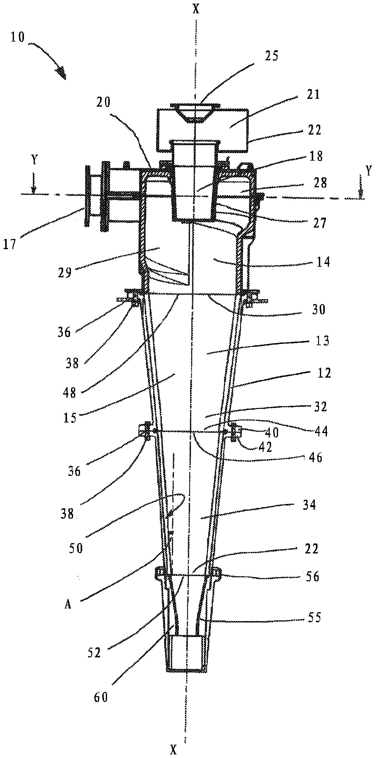
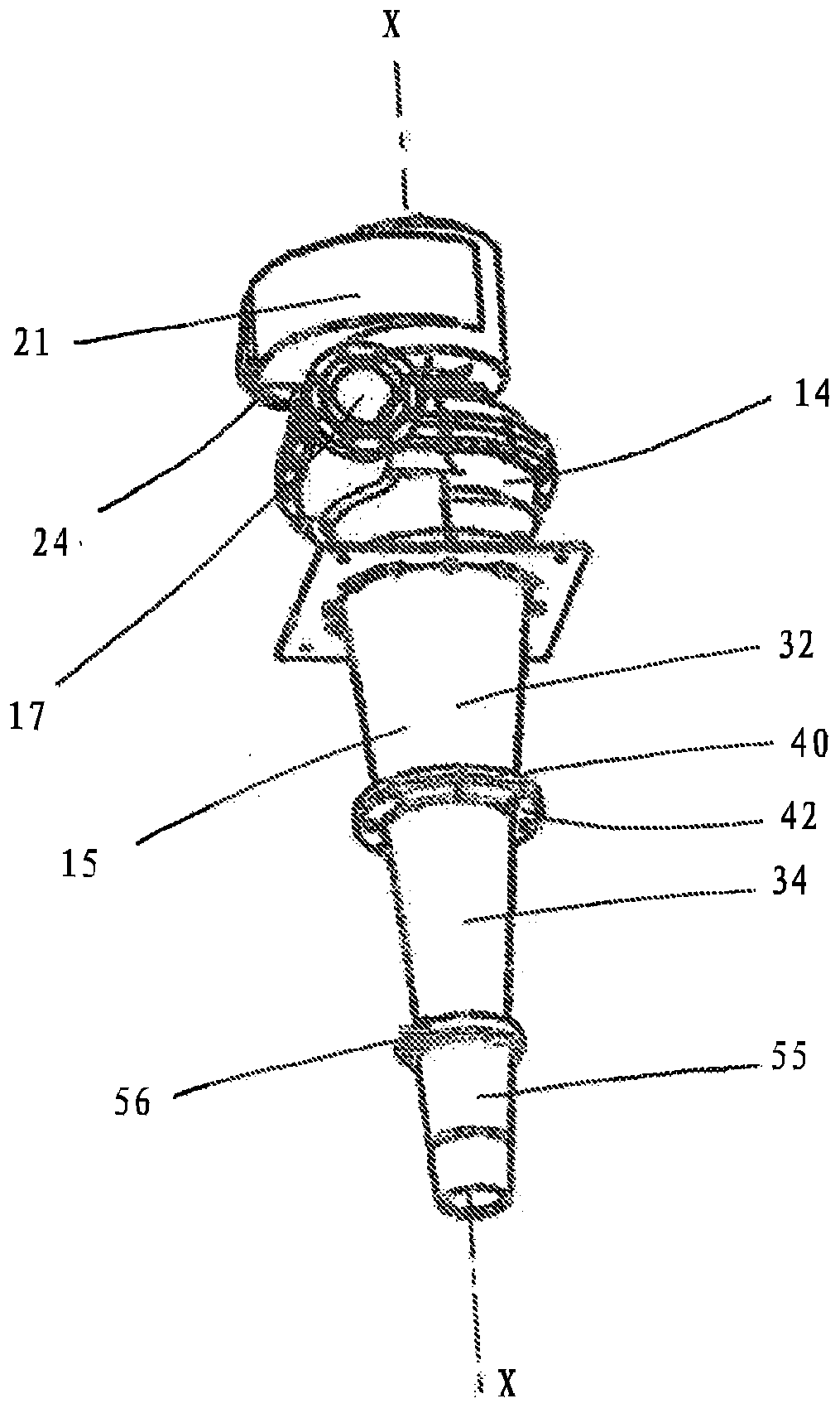
[0030] In use, a hydrocyclone is usually arranged vertically or nearly vertically with its central axis X-X. refer to figure 1 , shows a schematic cross-sectional view of a hydrocyclone 10 comprising a main body 12 having a chamber 13 defined therein. Chamber 13 includes an inlet (or feed) section 14 and a conical separation section 15 . The hydrocyclone also includes a cylindrical feed inlet port 17 of circular cross-section for feeding the particle-containing mixture in the form of a particle slurry into the inlet portion 14 of the chamber 13 .

[0031] Centrally located in the flat, disc-shaped upper (top) wall 20 of the chamber 13 is an overflow outlet (h...


PUM


Abstract

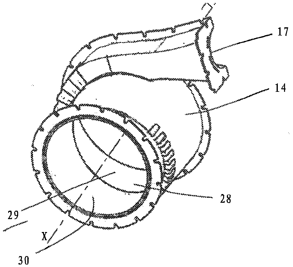
A hydrocyclone (10) is disclosed in which the inlet section (14) of the chamber (13) has a curved inner side wall surface (29) which is generally in the shape of a volute (28), for directing materialreceived in use from the feed inlet port (17) in a rotational motion. In the embodiment shown, the volute (28) is ramped axially downward within the inlet section (14), in a direction towards the conical separating section (15), and turns through an angle of more than 270 angle degrees. The conical section has a central axis X-X, and comprises two segments 32, 34 each being of a frustoconical shape, and joined together end to end to form a generally conical separating chamber (15). An internal angle A located between an inner wall surface (50) of the so-formed conical separating chamber (15) and a line parallel to the central axis X-X is ideally less than an angle of 8 degrees, to provide a hydrocyclone design with beneficial operating parameters.

Description

technical field [0001] The present invention relates generally to hydrocyclones, and more particularly, but not exclusively, to hydrocyclones suitable for use in the mineral and chemical processing industries. The invention also relates to the design of hydrocyclones as a way of optimizing their performance. Background technique [0002] A hydrocyclone separates suspended matter entrained in a flowing liquid (such as a mineral slurry) into two discharge streams by generating centrifugal force therein as the liquid passes through the conical chamber. Basically, a hydrocyclone comprises a conical separation chamber, generally substantially tangential to the axis of the separation chamber, with a feed inlet located at the end of the chamber with the largest cross-sectional dimension, and at the smaller An underflow outlet at the end, and an overflow outlet at the larger end of the chamber. [0003] The feed inlet is configured to deliver liquid containing suspended matter int...

Claims


Application Information

Patent Timeline
Patent Type & Authority Applications(China)
IPC IPC(8): B04C5/04
CPCB04C5/04B04C5/08B04C5/12B04C5/081
Inventor M.洛克耶D.斯威策J.洛佩兹E.塞佩达
Owner VULCO
Learn More