Radiotherapy apparatus

a radiation therapy and apparatus technology, applied in radiation therapy, accelerators, therapy, etc., can solve the problems of reducing shielding efficiency, adversely affecting the magnetic flux path through the enclosure and its ability to shield the linear accelerator it encases, and further limiting leakage, so as to achieve effective magnetic shielding, and high magnetic permeability material

Pending Publication Date: 2021-09-23
ELEKTA AB
View PDF4 Cites 1 Cited by
  • Summary
  • Abstract
  • Description
  • Claims
  • Application Information

AI Technical Summary

Benefits of technology

[0011]Such an enclosure, or can, of high magnetic permeability material provides a continuous low reluctance path for magnetic flux around substantially the entire periphery of the linear accelerator (the only breaks in the continuous high magnetic permeability material being the two apertures) and so provides an effective magnetic shield around the linear accelerator against static or slowly varying magnetic fields such as those typically present outside but close to a MRL. The high permeability material, provides a path for the magnetic, field lines outside and adjacent to the MRI system around the volume surrounded by the enclosure, in effect conducting the magnetic field around the waveguide enclosure and preventing it from penetrating inside the enclosure, thus shielding the waveguide within and the accelerating electrons / particles from the effects of the MRI system magnetic field, and this shielding effect is greater due to the continuous nature of the enclosure. The waveguide enclosure is also effective to reduce the effects of the varying magnetic field created by the system accelerating the electrons / particles on the MR. RF sensing system and so help prevent degradation of the MR imaging quality.
[0012]The optimal shape of waveguide enclosure to maximise conduction of magnetic field and so give maximum shielding would be a sphere; this is because the magnetic field flows through the high permeability material in a manner similar to a liquid flow, and discontinuities in the flow path lead to leakage, reducing shielding efficiency. A spherical waveguide enclosure would not be space-efficient, but the major dimension of a linear accelerator is along its linear axis, and we have found that a suitable compromise between the elimination of discontinuities in the shape of the wave guide enclosure which is still effective in preventing flux leakage and is reasonably straightforward to manufacture is for the cross-section of the enclosure transverse to the linear axis to be continuously curved, with substantially no discontinuities in shape. Thus the waveguide enclosure could be cylindrical, and not necessarily circular in cross-section (it could be oval or even pear-shaped in cross-section). The “cylindrical” enclosure could be closed at either end by planar, stepped or curved end caps of high magnetic permeability material (the end cap adjacent the MRI system is the interface flange), which are easy to manufacture and to fix to the enclosure—such an arrangement would produce a discontinuity where the end caps meet around the end circumference of the enclosure, but we have found that in practice the flux leakage such a discontinuity allows is small, and can be predicted and compensated for by other design features—the cylindrical parts and the end caps are manufactured with precise dimensions so that where they meet they are in substantially continuous contact around the entire circumference of the cylindrical parts.
[0013]The enclosure may be fabricated in a plurality of separate or discrete parts, provided that it extends over substantially all of the accelerator waveguide so as to provide maximum shielding of the linear accelerator. The non-unitary (i.e. formed of several separate parts joined together to form a substantially continuous shield) nature of the waveguide enclosure is deliberate, as this facilitates manufacture and installation of the enclosure, and installation, maintenance and replacement of the linear accelerator it shields; however, such an arrangement can also adversely affect the magnetic flux path through the enclosure and its ability to shield the linear accelerator it encases. It is therefore important that the separate parts of the waveguide enclosure are solidly but releasably connected together, in such a way that there are no gaps through which magnetic field lines could penetrate or from which magnetic flux could leak. The separate parts are preferably formed with overlapping joints, and abutting surfaces are preferably complementarily shaped and / or of complex, labyrinthine shape (so that the path from the interior to the exterior of the waveguide is labyrinthine, so that the path curves back on itself, for example) so as to minimise magnetic flux leakage. Such leakage may be further limited by ensuring that overlapping joints are fillet welded together, and / or joined by extensive arrays of mechanical fasteners (also preferably of high permeability material).
[0014]The enclosure may have an outwardly-extending collar portion, and this is preferably sized and configured to surround the RF guide, the piping and the cabling over at least a part of their length extending away from the enclosure. This collar helps prevent electromagnetic field leakage into or out of the waveguide enclosure, and the more tightly the collar wraps around the RF guide, the piping and the cabling the more effective the reduction in leakage. It may be suitable for the collar portion to have in cross-section a portion surrounding the RF guide (which is usually square or rectangular) and an adjacent (preferably contiguous) protrusion which surrounds the piping and cabling. This enables the cross-sectional area of the collar to be minimised and thus minimises leakage. The protrusion can be sized and configured to allow the piping and cabling to, run largely parallel within the collar portion, which means that any electromagnetic leakage must travel along the collar and, as this can be oriented so as to point away from the waveguide accelerator and the MRI system, this reduces the effects of any leakage between these elements. As with the main part of the waveguide enclosure surrounding the linear accelerator, the design of this collar should minimise discontinuities in shape, accordingly the collar is curved gently—i.e. it has, in cross-section, rounded corners.

Problems solved by technology

The optimal shape of waveguide enclosure to maximise conduction of magnetic field and so give maximum shielding would be a sphere; this is because the magnetic field flows through the high permeability material in a manner similar to a liquid flow, and discontinuities in the flow path lead to leakage, reducing shielding efficiency.
The non-unitary (i.e. formed of several separate parts joined together to form a substantially continuous shield) nature of the waveguide enclosure is deliberate, as this facilitates manufacture and installation of the enclosure, and installation, maintenance and replacement of the linear accelerator it shields; however, such an arrangement can also adversely affect the magnetic flux path through the enclosure and its ability to shield the linear accelerator it encases.
Such leakage may be further limited by ensuring that overlapping joints are fillet welded together, and / or joined by extensive arrays of mechanical fasteners (also preferably of high permeability material).

Method used


Image

  • Radiotherapy apparatus
  • Radiotherapy apparatus
  • Radiotherapy apparatus

Examples


Embodiment Construction

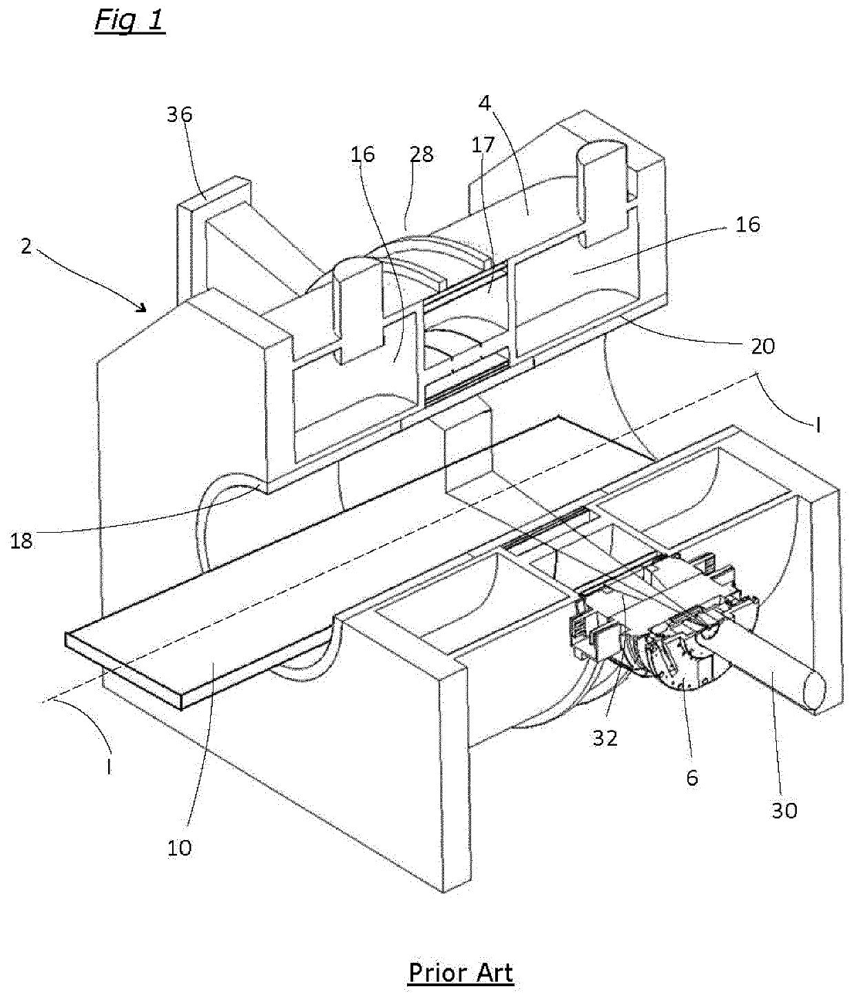
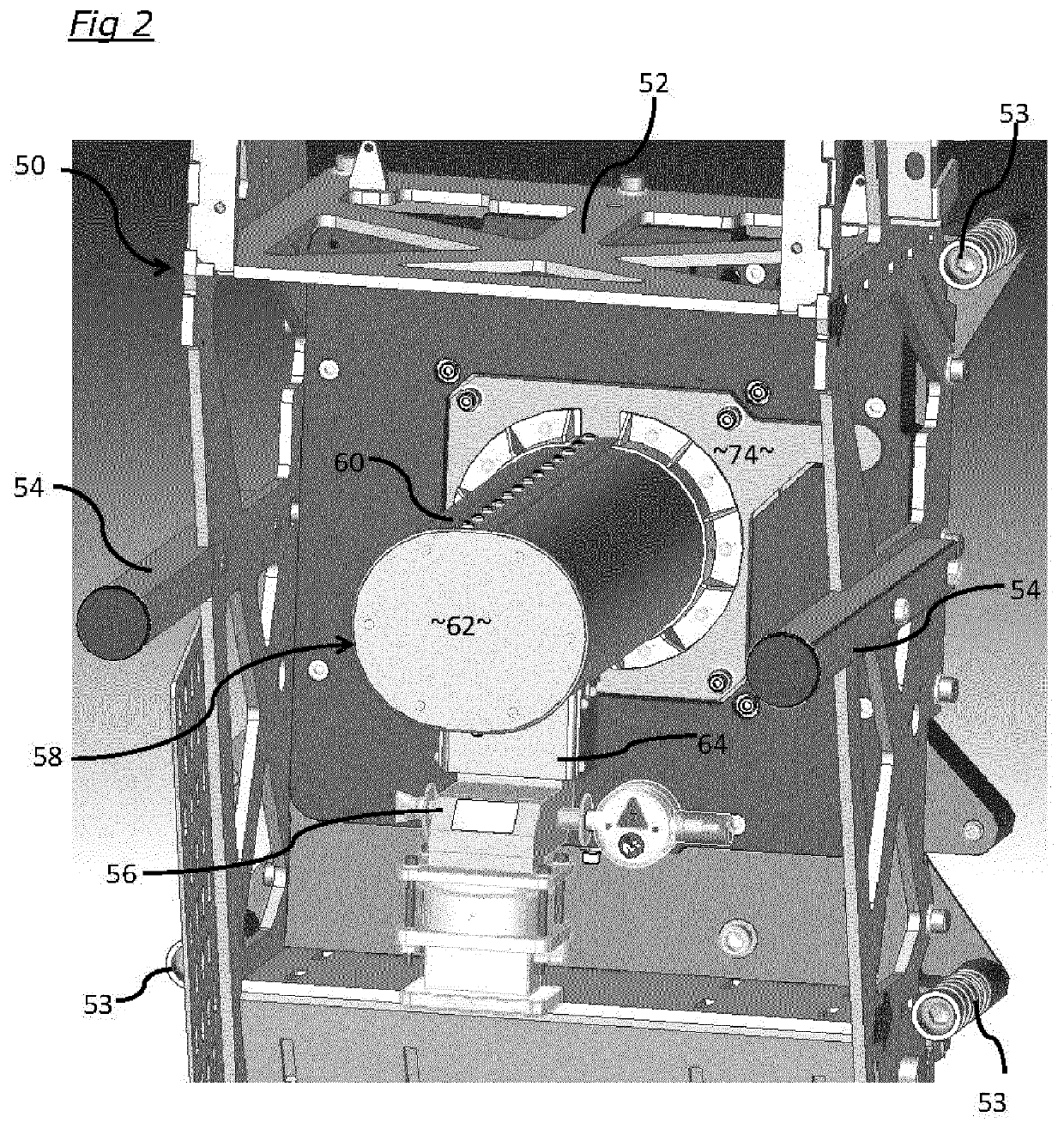
[0024]The conventional MRL system shown in FIG. 1 is described above. FIG. 2 shows a linear accelerator assembly 50 which is enclosed in an open framework or cradle 52 for mounting to the rotatable gantry 28 of the MRL by way of attachments 53; although not shown in FIG. 2, the gantry would be behind the assembly 50 shown in FIG. 2, with the legs 54 extending generally radially outwardly from the axis II of the MRI apparatus (as shown in FIG. 1). The linear accelerator comprises an RF guide 56 for electrons emitted by an electron source (not shown) which causes electrons to be injected upwardly in the drawing to a linear accelerator waveguide 100 (which is not visible in FIG. 1 because it is hidden within the waveguide enclosure 58, but is shown in FIG. 6) but the waveguide turns the electrons so that they move in a different direction, and accelerates the electrons radially inwardly with respect to the MRI system, into the plane of the drawing, roughly parallel with the legs 54. Th...


PUM


Abstract

A radiotherapy apparatus adapted for use with a Magnetic Resonance Imaging (MRI) system, the radiotherapy apparatus comprising a linear accelerator, the linear accelerator including an electron source. In the linear accelerator electrons which are introduced by the source are accelerated to impact on a target and produce a beam of radiotherapeutic radiation. The linear accelerator has an accelerator waveguide within which the electrons are accelerated and an external waveguide enclosure; this enclosure extends substantially continuously over the accelerator waveguide. The waveguide enclosure is formed of a high magnetic permeability material and has a first aperture for the beam of radiotherapeutic radiation where the beam exits the waveguide enclosure and enters the MRI system and a second aperture for an RF guide for the introduction of electrons into the accelerator waveguide and for electrical lines for the particle source and coolant lines for the waveguide to pass through the enclosure and no other openings. The waveguide enclosure is preferably fabricated in a plurality of discrete parts.

Description

FIELD OF THE INVENTION[0001]The present invention relates to radiotherapy apparatus, particularly but not exclusively to Magnetic Resonance (MR) guided linear accelerator apparatus.BACKGROUND ART[0002]Radiotherapeutic apparatus is well-known, in which a source of radiation emits a beam of radiation that is directed toward a patient in order to destroy or otherwise harm cancerous cells within the patient. Many designs of radiotherapy apparatus employ a radiation source such as a linear accelerator (linac) for high-energy (MV) X-radiation, or an isotopic source such as Co-60 mounted on an elongate gantry arm that is rotatable around a patient support on which a patient can be placed for treatment. The source is rotatable so it can be rotated around the patient in order to irradiate the desired region from a number of different directions, thereby reducing the dose applied to healthy tissue outside the desired region. It is normal to collimate the beam so as to limit its spatial extent...

Claims


Application Information

Patent Timeline
Patent Type & Authority Applications(United States)
IPC IPC(8): A61N5/10
CPCA61N5/1049A61N2005/1055A61N2005/1094A61N5/1081A61N5/10H05H7/22H05H2277/11
Inventor SHINTON, IANHARASIMOWICZ, JANUSZCHADWICK, GEORGEDIXON, PAUL
Owner ELEKTA AB
Why Eureka
Try Eureka