Integrated drain mast structure

Active Publication Date: 2019-09-12
SENIOR IP GMBH
View PDF0 Cites 4 Cited by
  • Summary
  • Abstract
  • Description
  • Claims
  • Application Information

AI Technical Summary

Benefits of technology

[0011]The tube section includes a plurality of generally aligned fluid passages extending from an upper end of the tube section to a lower end of the tube section with each fluid passage having a peripheral surface of substantially equal thickness throughout the self-supporting tube section, at least a portion of which surface is common with a portion of a peripheral surface of at least one other aligned fluid passage. The upper end of each fluid passage within the tube section is configured to be in fluid communication with one or more sources of fluid, respectively. The cross sectional area of the self-supporting tube section substantially corresponds to the collective width of the plurality of generally aligned fluid passages, so as to minimize sai

Problems solved by technology

The detection of fluid leaking from a turbine engine may indicate that an engine component has failed or is likely to fail in the near future, if no action is taken.
A visual pre-flight inspection of the drain line fairing may reveal fluids leaking from the engine which may be an indication of a critical component failure or an indication of a potential future failure—each of which may result in engine failure leading to a potentially catastrophic result.
While multiple drain outlets are provided in the fairing, in some cases it may be difficult to confirm from which outlet any one or more fluids leaked, making identification of the engine component requiring attention difficult, if not impossible.
Regardl

Method used


Image

  • Integrated drain mast structure
  • Integrated drain mast structure
  • Integrated drain mast structure

Examples


Example

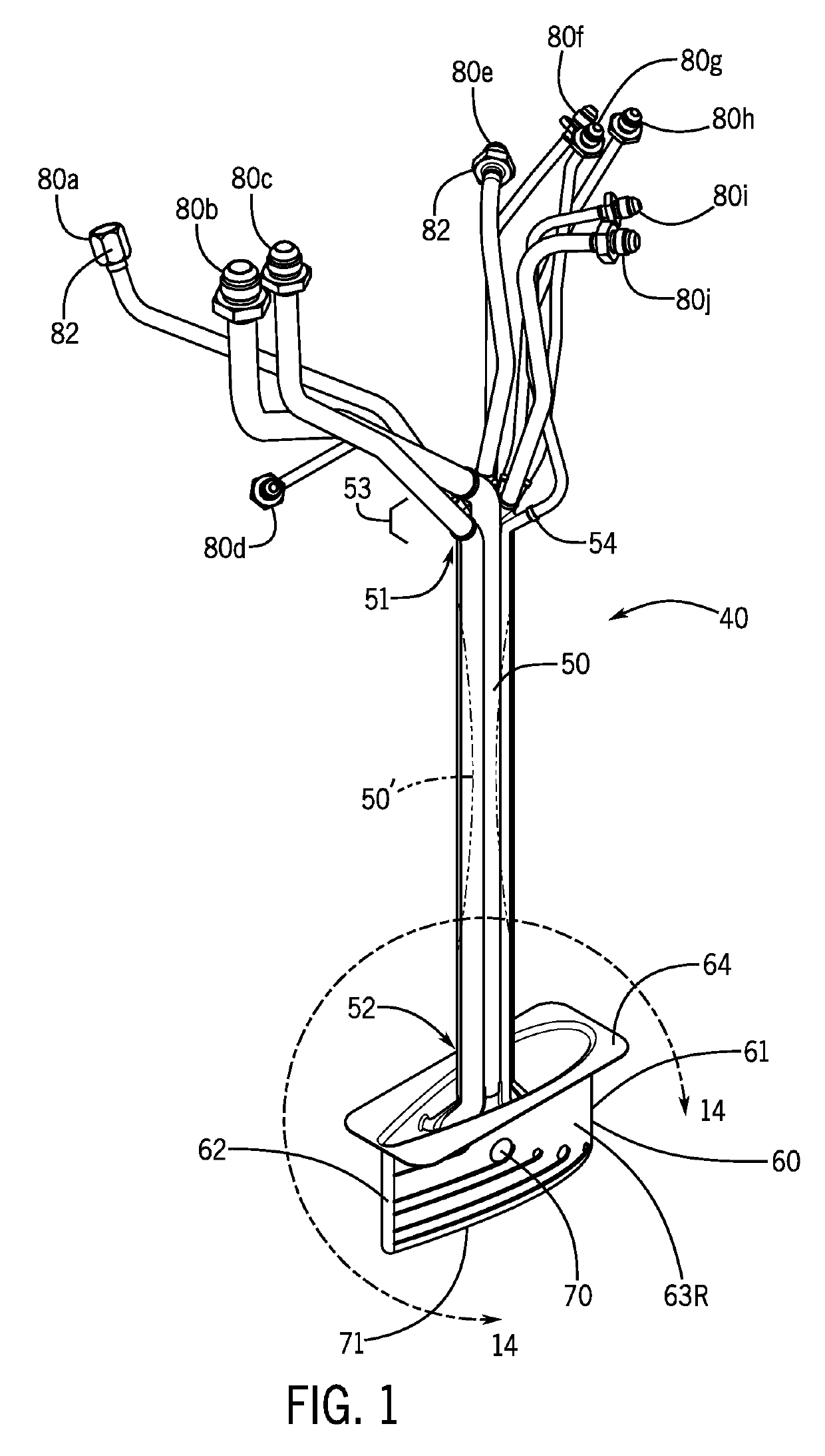
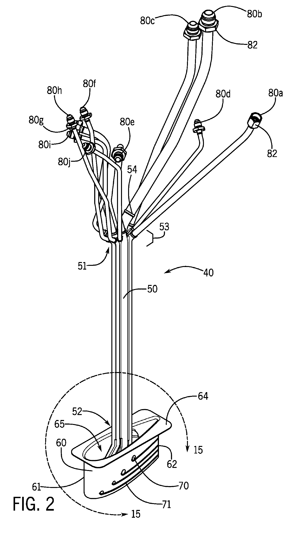
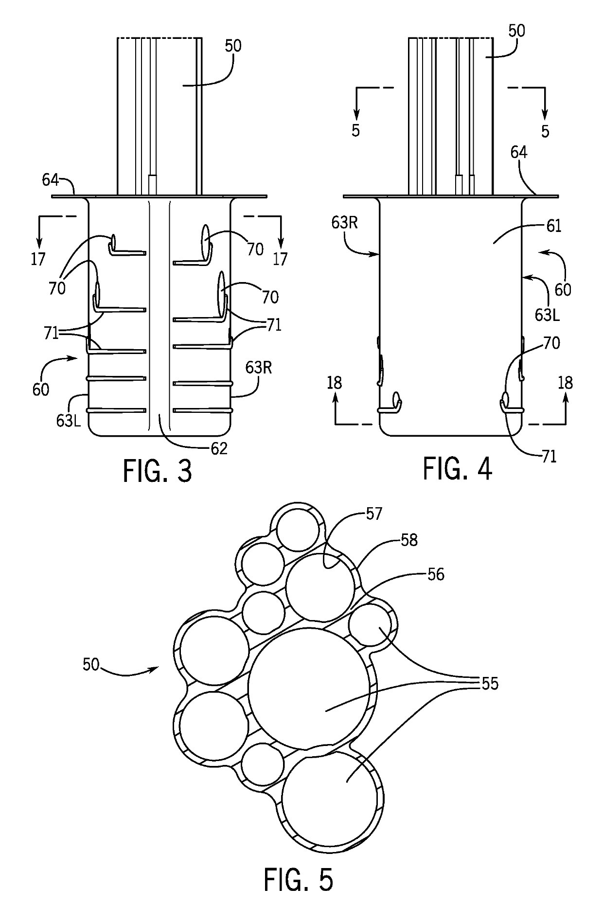
[0048]FIGS. 1 and 2 of the drawings illustrate a first embodiment of the integrated design mast structure 40 of the present invention and, in particular, a light-weight, self-supporting tube section 50 and fairing 60. Tube section 50 is intended to be installed within the space enclosed by an aircraft engine or fuselage. In use on the bottom an aircraft engine cowling, fairing 60 extends through the aircraft engine cowling for positioning in the airstream. Tube section 50 comprises a unitary structure including plurality of generally aligned fluid passages 55 (as shown in FIG. 5) extending from upper end 51 to lower end 52 of tube section 50. Substantially aerodynamic fairing 60 includes a plurality of fairing fluid passages 90 (as shown in FIGS. 14-18) each of which fairing fluid passages 90 is in operable fluid communication with a corresponding fluid passage 55 of tube section 50. Fairing 60 includes leading surface 61, trailing surface 62 and fluid outlets 70 located along both ...


PUM


Abstract

An integrated drain mast structure for use in draining fluids emanating from aircraft components, such as turbine engines and fuselages, for facilitating the detection of fluids leaking from said components. A self-supporting tube section including a plurality of generally aligned fluid passages each having a peripheral wall, at least a portion of which is common with at least a portion of another aligned adjacent fluid passage is connected to one or more of these aircraft components. An aerodynamic fairing includes a plurality of fairing fluid passages each connected to a respective fluid passage of the tube section and having respective fluid outlets. The tube section and fairing section can comprise a single integral structure.

Description

FIELD OF THE INVENTION[0001]The present invention relates to aircraft components from which fluids are drained, including gas turbine engines used in aircraft. In the case of gas turbine engines, an integrated drain mast structure is used to drain fluids emanating from various gas turbine engine components, and to facilitate the detection of fluids leaking from those components. Drain mast structures can also be used in conjunction with the fuselage of an aircraft to also facilitate fluid drainage, together with the detection and identification of the nature of those fluids.BACKGROUND OF THE INVENTION[0002]Gas turbine engines used in modern aircraft are complex pieces of equipment whose proper operation and reliability are essential to safe flight. Modern gas turbine engines incorporate critical components which often generate, convey, consume and / or contain fluids. For example, components, such as fuel pumps and hydraulic pumps, distribute and control the flow of jet fuel and hydra...

Claims


Application Information

Patent Timeline
IPC IPC(8): B64C1/14
CPCB64C1/1453B64D29/00B64D1/16F01D25/32
Inventor PARKER, MATTHEW J.MISTRY, SHAILESH N.POSSERT, ERIC M.
Owner SENIOR IP GMBH
Why Eureka
Try Eureka