
Rear view mirror

Inactive Publication Date: 2010-04-29
FORD GLOBAL TECH LLC
View PDF25 Cites 4 Cited by
  • Summary
  • Abstract
  • Description
  • Claims
  • Application Information

AI Technical Summary

Benefits of technology

[0015]More drivers will be able to adjust mirrors properly if an affirmative method is provided for determining when the rear view mirror is properly adjusted. Properly adjusted mirrors afford the driver an improved view of the objects in the vehicle's vicinity which reduces or eliminates blind spots.
[0016]The cross-sectional area of the mirror may be minimized if the manufacturer can be confident that drivers properly adjust the mirrors. In some cases, manufacturers place larger mirrors on vehicles than strictly necessary, to overcome the problem of maladjusted mirrors giving inappropriate views. With assurance that the viewing angle is adjusted properly, manufacturers would not need to compensate for maladjusted mirrors. The benefits of smaller mirrors are improved fuel economy by reducing the area of cross-section of the vehicle with respect to the direction of travel. Also, rear view mirrors can be a source of wind noise, which would be lessened with smaller mirrors. Finally, mirrors are known to be clipped by encounters with fixed or moving objects. Examples of fixed objects are mail boxes, garage door openings, toll booths, and telephone poles. Any decrease in the size of the mirror can reduce the overall width of the vehicle, which allows for access to tighter places and a reduced chance of hitting the mirror with another object.

Problems solved by technology

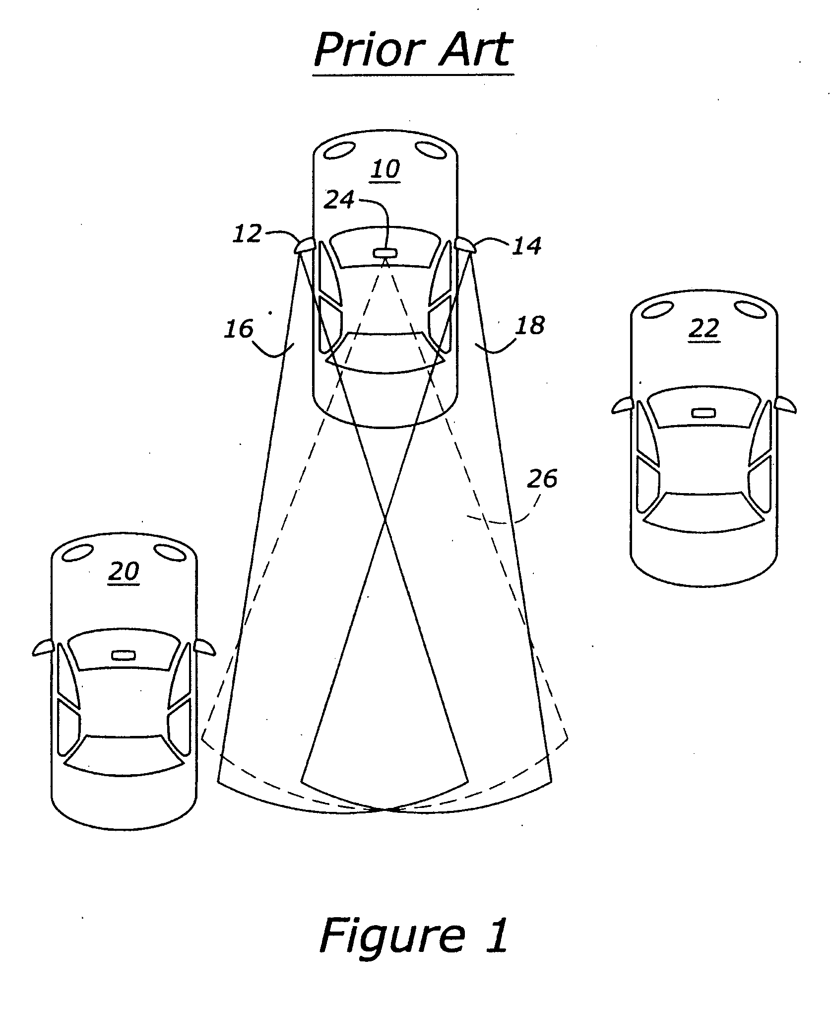
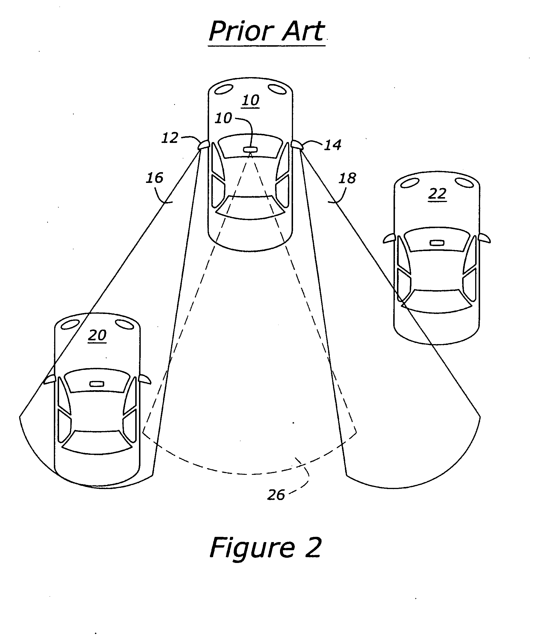
However, such a position in FIG. 3 corresponds to the improper adjustment illustrated in FIG. 1.
Larger mirrors increase weight and aerodynamic drag to the vehicle, both of which penalize fuel economy.
Also, the farther the mirrors extend from the vehicle, the greater the likelihood that the vehicle will clip an object in tight conditions such as entering a narrow garage opening or when moving the car close to a booth for collecting a parking ticket or paying a toll.

Method used


Image

  • Rear view mirror
  • Rear view mirror
  • Rear view mirror

Examples


Embodiment Construction

)

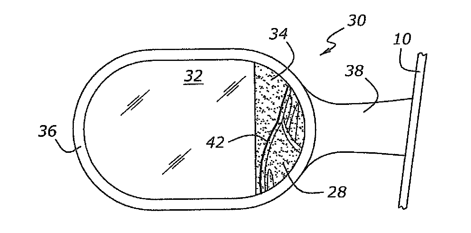
[0029]Referring to FIG. 4, a mirror assembly 30 having a first surface 32 (alternately called a viewing section) and a second surface 34 (alternately called an alignment section) is shown mounted in housing 36. Housing 36 has an arm 38 for attaching the mirror assembly 30 to vehicle 10. In one embodiment, second surface 34 is less reflective than first surface 32. Second surface 34 is etched with a targeting feature, which in one embodiment is a cross-hair 40 to aid in aligning the mirror assembly 30 properly. In particular, a feature on the car, such as a door handle (not shown), is designated to be the target point for cross-hair 40 to ensure suitable alignment of mirror assembly 30.

[0030]Alternatively, in FIG. 5, the targeting feature is a targeting outline 42 for aligning the first surface 32 of mirror assembly 30 is an outline of the outside surface of the vehicle. When, the image of the outside of vehicle 28 aligns with targeting outline 42, the first surface 32 of the mirror...


PUM


Abstract

A rear view mirror assembly is disclosed in which the mirror has a viewing section and an alignment section meeting to form a reflex angle. The alignment section is etched with a targeting image: a cross-hair or the side surface of the vehicle. When the targeting image is aligned with appropriate feature on the side of the vehicle, the reflex angle is such that the mirror is properly aligned. Also disclosed is a mirror assembly having viewing section and an alignment section with a clear protective outer layer a selective acceptance layer below the clear protective outer layer, and a colored substrate below the selective layer. When the vehicle operator can see the colored substrate through the selective acceptance layer, which transmits only normal light, the mirror is properly aligned.

Description

BACKGROUND OF THE INVENTION[0001]1. Field of the Invention[0002]The present development relates to a rear view mirror that facilitates properly aligning the mirror.[0003]2. Background of the Invention[0004]Mirror systems are provided on automotive vehicles to aid the operator of the vehicle in viewing other vehicles while merging, lane changing, turning, reversing, etc. Mirrors can provide a view of the vehicles and objects in the vicinity of the operator's vehicle. However, the effectiveness of that view depends on proper alignment of the mirrors. It is known in the art, through customer interviews, car clinics, and survey comments that many vehicle operators do not align their mirrors in an orientation which provides the most information to the operator.[0005]In particular, it is common for drivers to position their exterior side mirrors so that they can see the edge of their own vehicle 10. As illustrated in FIG. 1, side mirrors 12 and 14 are adjusted such that their respective v...

Claims


Application Information

Patent Timeline
IPC IPC(8): B60R1/08
CPCB60R1/08B60R1/025
Inventor FORBES, JAMES WENDELLPETNIUNAS, ALEXANDER
Owner FORD GLOBAL TECH LLC
Learn More