Transmission line including first and second signal conductor patterns separated by a third non-signal conductor pattern with specified dimensional relationships there between

a technology of signal conductor and dimensional relationship, applied in the field of transmission lines, can solve the problems of complicated manufacturing and complicated manufacturing, and achieve the effects of reducing manufacturing complication, reducing manufacturing complication, and reducing manufacturing complication

Active Publication Date: 2019-11-26
YAZAKI CORP
View PDF6 Cites 0 Cited by
  • Summary
  • Abstract
  • Description
  • Claims
  • Application Information

AI Technical Summary

Benefits of technology

[0007]The invention has been accomplished in order to solve such problems inherent in the related art. An object of the invention is to provide a transmission line in which unnecessary coupling is suppressed while a complication in manufacturing is suppressed, and in which characteristic impedance can be made stable and a conductor loss can be reduced.
[0009]According to the transmission line, the relation S≥2w is satisfied, wherein S expresses the distance between the first and second conductor patterns and w expresses the width of each of the first and second conductor patterns. Accordingly, the distance between the conductor patterns, in each of which a signal is made to flow, is secured sufficiently so that an influence caused by unnecessary coupling can be suppressed. In the range where the distance is satisfied, the relation 0.5w≤S1≤1.5w and the relation 0.5w≤S2≤1.5w are satisfied, wherein S1 expresses the distance between the first conductor pattern and the third conductor pattern and S2 expresses the distance between the second conductor pattern and the third conductor pattern. Accordingly, the distance between each of the first and second conductor patterns and the third conductor pattern in which no signal is made to flow is secured to some degree so that characteristic impedance can be made stable. At the same time, the distance between each of the first and second conductor patterns and the third conductor pattern in which no signal is made to flow is set within a predetermined range so that an attenuation amount of a signal can be suppressed. Particularly, in the aforementioned configuration, the third conductor pattern is provided between the first and second conductor patterns. The distance between each of the first and second conductor patterns and the third conductor pattern may be adjusted if necessary. Accordingly, a hole and offset configuration, adjustment of surface roughness, etc. can be dispensed with. Thus, complication in manufacturing can be suppressed. Consequently, it is possible to provide the transmission line in which the unnecessary coupling is suppressed while the complication in manufacturing is suppressed, and in which the characteristic impedance can be made stable and a conductor loss can be reduced.
[0011]According to the transmission line, the first, second and third conductor patterns are substantially the same in width and substantially the same in thickness. Accordingly, three patterns which are the same in shape can be formed as the first, second and third conductor patterns so that the complication in manufacturing can be suppressed more greatly.
[0013]According to the invention, it is possible to provide a transmission line in which unnecessary coupling is suppressed while a complication in manufacturing is suppressed, and in which characteristic impedance can be made stable and a conductor loss can be reduced.

Problems solved by technology

This complicates manufacturing.
For this reason, the number of steps of chemically or physically modifying the surfaces of the conductors increases to thereby complicate manufacturing.

Method used


Image

  • Transmission line including first and second signal conductor patterns separated by a third non-signal conductor pattern with specified dimensional relationships there between
  • Transmission line including first and second signal conductor patterns separated by a third non-signal conductor pattern with specified dimensional relationships there between
  • Transmission line including first and second signal conductor patterns separated by a third non-signal conductor pattern with specified dimensional relationships there between

Examples


Embodiment Construction

[0020]The invention will be described below in accordance with a preferred embodiment. Incidentally, the invention is not limited to the embodiment which will be described below but may be changed suitably without departing from the gist of the invention. In addition, in the embodiment which will be described below, there is a place from which illustration or description of a part of the configuration is omitted. However, it is a matter of course that, as to details of the omitted technique, a known or well-known technique can be applied as long as the technique does not cause any inconsistency with contents which will be described below.

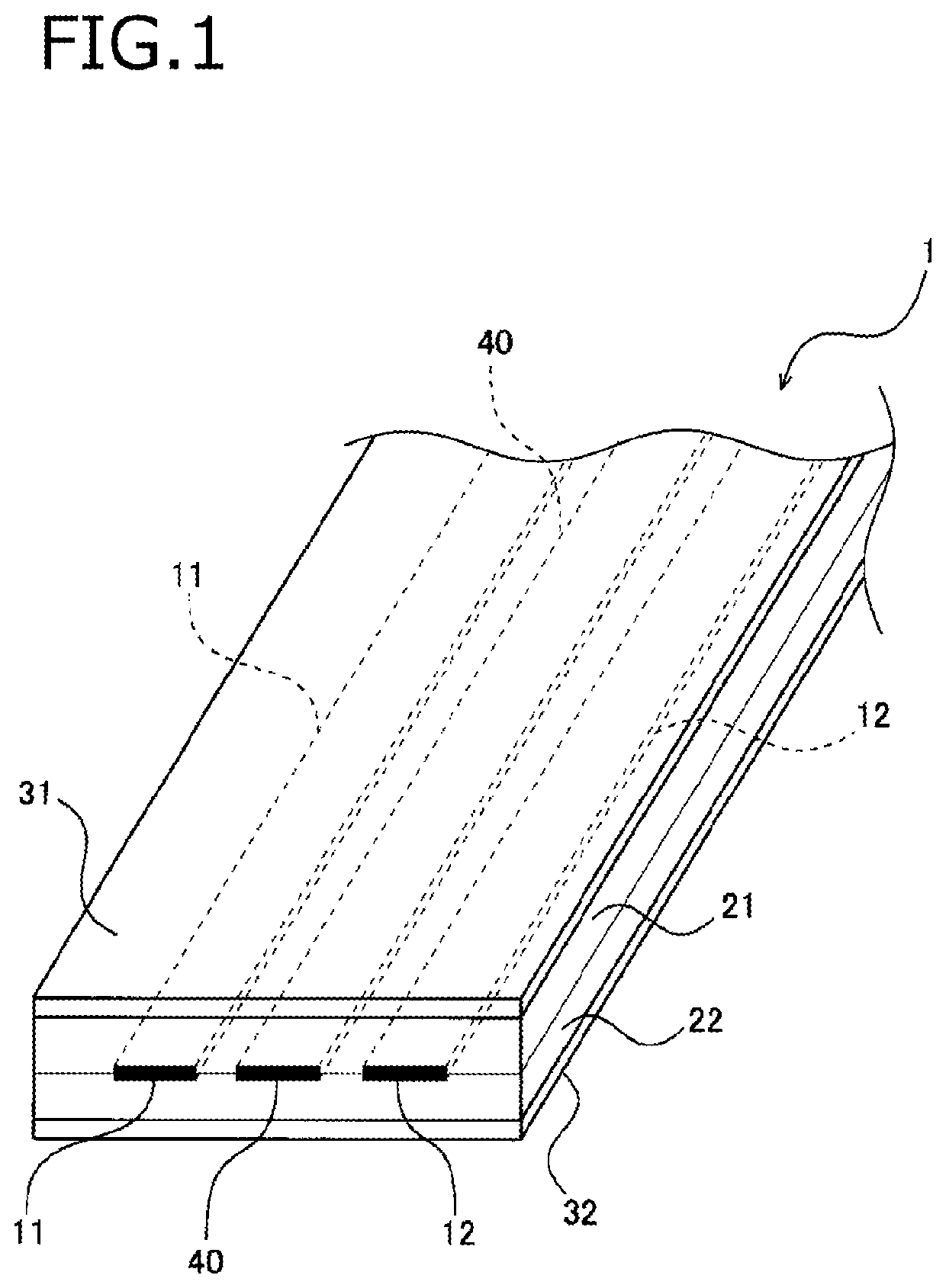
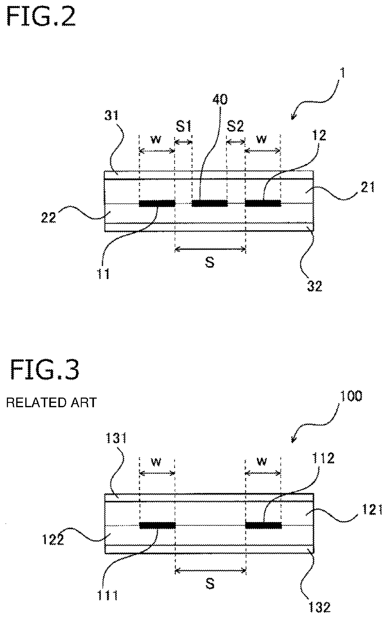
[0021]FIG. 1 is a perspective view showing a transmission line according to the embodiment of the invention. FIG. 2 is a sectional view of the transmission line shown in FIG. 1. As shown in FIG. 1 and FIG. 2, the transmission line 1 includes first and second conductor patterns 11 and 12, and first and second insulating layers 21 and 22. The first an...


PUM


Abstract

A transmission line includes first and second conductor patterns that serve as signal transmission paths, first and second insulating layers that hold the first and second conductor patterns therebetween, and a third conductor pattern that is arranged between the first and second conductor patterns. No signal is transmitted through the third conductor pattern. A relation 0.5w≤S1≤1.5w and a relation 0.5w≤S2≤1.5w are satisfied in a range of a relation S≥2w, wherein S expresses a distance between the first conductor pattern and the second conductor pattern, w expresses a width of each of the first conductor pattern and the second conductor pattern, S1 expresses a distance between the first conductor pattern and the third conductor pattern, and S2 expresses a distance between the second conductor pattern and the third conductor pattern.

Description

CROSS REFERENCE TO RELATED APPLICATIONS[0001]This application is based on Japanese Patent Application (No. 2016-209291) filed on Oct. 26, 2016, the contents of which are incorporated herein by reference.BACKGROUND OF THE INVENTION1. Field of the Invention[0002]The present invention relates to a transmission line.2. Description of the Related Art[0003]In the related art, transmission lines in which conductor patterns are formed to be held between insulating layers have been proposed. In such a transmission line, a plurality of conductor patterns may be provided in parallel. For example, it has been also proposed that when the plurality of conductor patterns are used as signal wires, a hole is formed between adjacent ones of the conductor patterns in order to suppress unnecessary coupling between the adjacent ones of the signal wires. Further, it has been also proposed that the conductor patterns are offset in an up / down direction. In addition, it has been also proposed that ground pa...

Claims


Application Information

Patent Timeline
Patent Type & Authority Patents(United States)
IPC IPC(8): H01P3/08
CPCH01P3/085H01P3/08H01P3/02H01P3/026H01B7/0838H04B3/48H04B3/50H04B3/00
Inventor SHIRAI, MIZUKIKONDO, HIROKI
Owner YAZAKI CORP
Why Eureka
Try Eureka