Directional coupler

a directional coupler and directional coupler technology, applied in the direction of coupling devices, waveguide type devices, basic electric elements, etc., can solve the problems of degrading the characteristics of the coupler, difficult to space the inductor and main and secondary lines apart from each other in a miniaturized coupler, etc., to facilitate the degradation of the characteristics of the directional coupler, hinder unnecessary coupling, and increase the flexibility of arranging the inductors

Pending Publication Date: 2022-03-10
MURATA MFG CO LTD
View PDF0 Cites 0 Cited by
  • Summary
  • Abstract
  • Description
  • Claims
  • Application Information

AI Technical Summary

Benefits of technology

[0007]The present disclosure provides a compact directional coupler with excellent characteristics having a main line, a secondary line, and a termination impedance circuit for providing an adjustable impedance (in particular, adjustable inductance) for the secondary line.
[0009]In the directional coupler according to the present disclosure, the maximum amount of inductance required for the variable inductor can be obtained by adding the inductances of the plurality of inductors coupled in series with each other. As such, the inductance of each of the plurality of inductors can be lower than the maximum amount of inductance required for the variable inductor, and the plurality of inductors can be downsized.
[0010]Because the plurality of inductors constituting the variable inductor can be downsized, it is possible to increase the flexibility in arranging the inductors. It is thus easy to place the inductors and the main line and the secondary line apart from each other in the miniaturized directional coupler.
[0011]This can consequently hinder unnecessary coupling between the inductors and the main line and the secondary line, and as a result, it is easy to prevent degradation of characteristics of the directional coupler due to unnecessary coupling, in particular, degradation of directivity and variations in the degree of coupling. Accordingly, a compact directional coupler with excellent characteristics can be implemented.

Problems solved by technology

An inductor of a large amount of inductance usually occupies a large area, and as a result, it is difficult to space the inductor and main and secondary lines apart from each other in a miniaturized coupler.
Consequently, unnecessary coupling may occur between the inductor and the main and secondary lines, which degrades characteristics of the coupler.

Method used


Image

  • Directional coupler
  • Directional coupler
  • Directional coupler

Examples


first embodiment

[0028]A directional coupler according to a first embodiment will be described by using as an example a high frequency coupler including a main line, a secondary line, and a variable terminator coupled to an end portion of the secondary line and configured to terminate the end portion of the secondary line with an adjustable impedance.

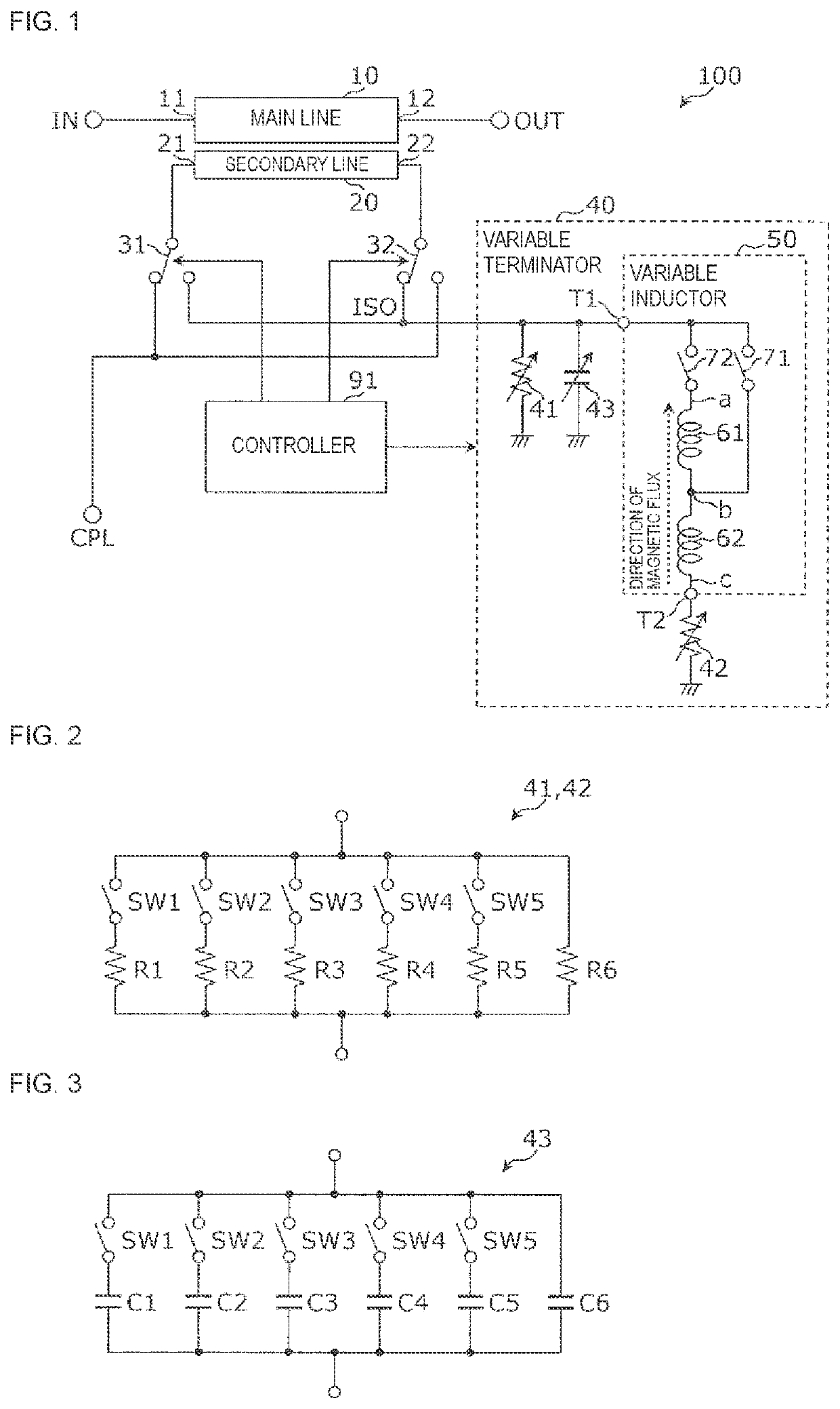
[0029]FIG. 1 is a circuit diagram illustrating an example of a configuration of the directional coupler according to the first embodiment.

[0030]As illustrated in FIG. 1, a directional coupler 100 is constituted by a main line 10, a secondary line 20, switches 31 and 32, a variable terminator 40, and a controller 91.

[0031]The main line 10 and the secondary line 20 are electromagnetically coupled to each other. As a result, when an end portion 22 of the secondary line 20 is terminated, a portion of a main signal transferred through the main line 10 from an end portion 11 to an end portion 12 is outputted as a detection signal from an end portion 21 of the...

second embodiment

[0107]A directional coupler according to a second embodiment will be described by using as an example a directional coupler formed as a module.

[0108]FIG. 11 is a circuit diagram illustrating an example of a configuration of the directional coupler according to the second embodiment.

[0109]As illustrated in FIG. 11, a directional coupler 101 differs from the directional coupler 100 in FIG. 1 in adding a variable matching circuit 80 and adding to a controller 92 a function of controlling the variable matching circuit 80. The variable matching circuit 80 is formed by a variable inductor 81 and a variable capacitor 82. The variable matching circuit 80 is coupled between an end portion for signal output of the secondary line 20 and the coupled port CPL. In FIG. 11, the main line 10 and the secondary line 20 of the directional coupler 101 are illustrated as an LC equivalent circuit.

[0110]FIG. 12 is a circuit diagram illustrating an example of a configuration of the variable matching circui...


PUM


Abstract

A directional coupler includes a main line, a secondary line, and a variable terminator. The variable terminator includes a variable inductor. The variable inductor includes a plurality of inductors coupled in series with each other between an end portion of the secondary line and the ground and switches configured to bypass at least one inductor of the plurality of inductors.

Description

CROSS REFERENCE TO RELATED APPLICATION[0001]This is a continuation of International Application No. PCT / JP2020 / 019828 filed on May 19, 2020 which claims priority from Japanese Patent Application No. 2019-096776 filed on May 23, 2019. The contents of these applications are incorporated herein by reference in their entireties.BACKGROUNDTechnical Field[0002]The present disclosure relates to a directional coupler.[0003]Directional couplers are basic components widely used for radio devices such as mobile terminal devices. For example, Patent Document 1 discloses a radio frequency coupler having a main line, a coupled line, and a termination impedance circuit capable of terminating a port of the coupled line with an adjustable impedance (for example, FIG. 16A in Patent Document 1). The termination impedance circuit disclosed in Patent Document 1 includes a plurality of inductors and a plurality of switches. In response to states of the plurality of switches, a particular number equal to ...

Claims


Application Information

Patent Timeline
Patent Type & Authority Applications(United States)
IPC IPC(8): H01P5/18
CPCH01P5/18H01P5/185
Inventor SEKI, KENTAKIM, RYANGSUSHIMIZU, KATSUYA
Owner MURATA MFG CO LTD
Why Eureka
Try Eureka