Conductive cover for dielectric filter, dielectric filter, dielectric duplexer, and communication apparatus

a technology of dielectric filters and conductive covers, applied in electrical devices, coupling devices, waveguides, etc., can solve problems such as deformation of conductive covers, and achieve the effect of preventing unnecessary coupling and small siz

Active Publication Date: 2005-07-05
MURATA MFG CO LTD
View PDF8 Cites 1 Cited by
  • Summary
  • Abstract
  • Description
  • Claims
  • Application Information

AI Technical Summary

Benefits of technology

[0017]According to the present invention, in a dielectric duplexer in which a plurality of resonator holes constitute a transmitting filter and a receiving filter in a single dielectric block, shaped portions of a conductive cover are provided between the transmitting filter and the receiving filter. This can prevent unnecessary coupling between the transmitting filter and the receiving filter. Thus, the entirety of the dielectric duplexer has a small size caused by closely disposing the transmitting filter and the receiving filter.

Problems solved by technology

Accordingly, there is a possibility that the conductive cover may be deformed by some external force while the dielectric filter is produced or when the finished dielectric filter is mounted on a circuit board in an electronic device, or after the mounting step.

Method used


Image

  • Conductive cover for dielectric filter, dielectric filter, dielectric duplexer, and communication apparatus
  • Conductive cover for dielectric filter, dielectric filter, dielectric duplexer, and communication apparatus
  • Conductive cover for dielectric filter, dielectric filter, dielectric duplexer, and communication apparatus

Examples


first embodiment

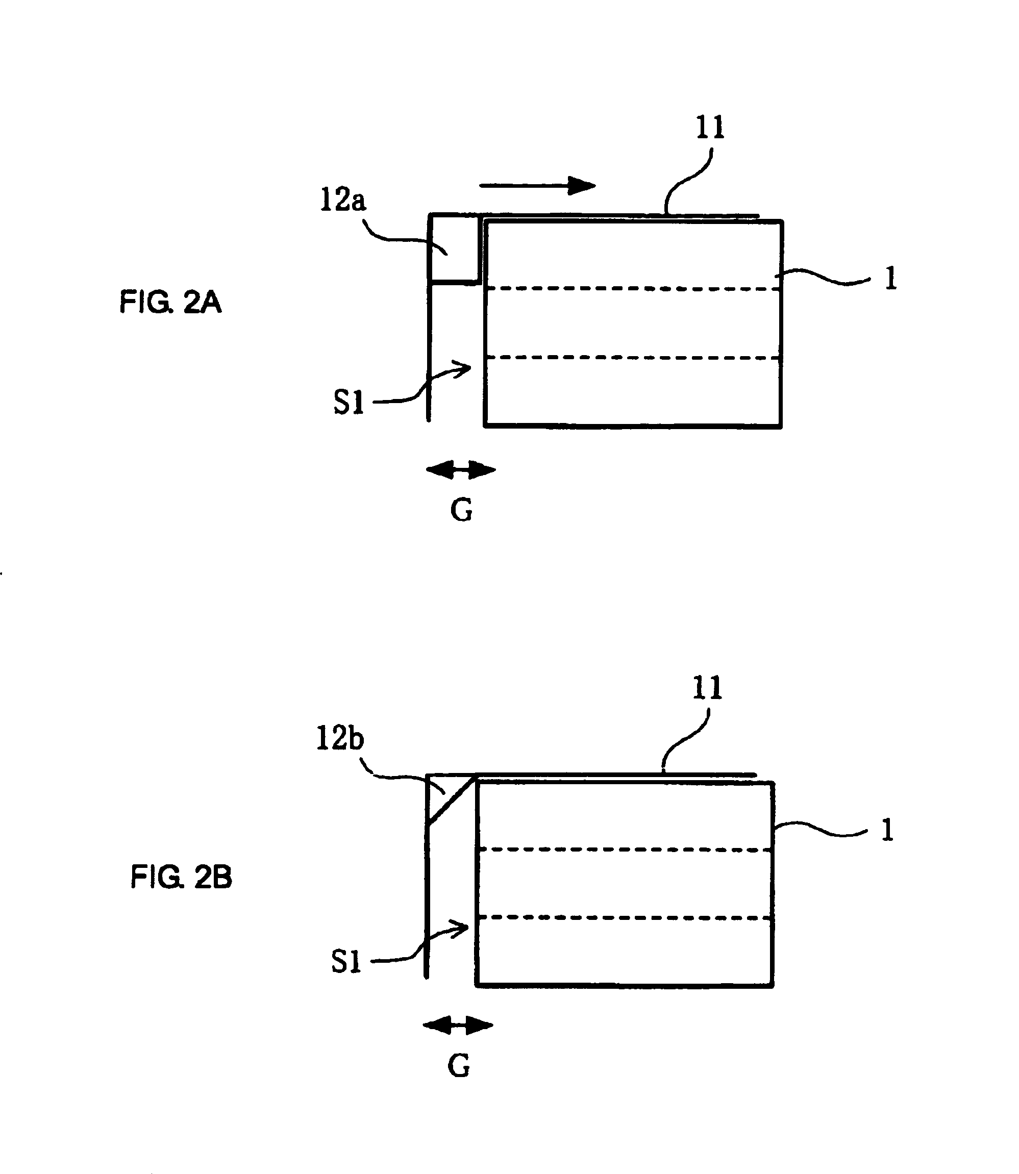
[0023]The structure of a dielectric filter according to the present invention is described below with reference to FIGS. 1A to 2B.

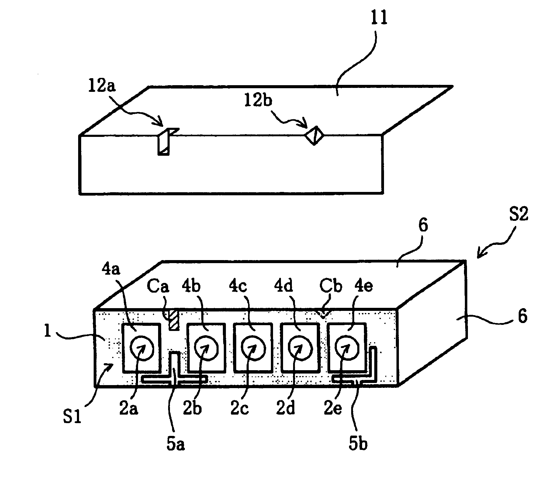
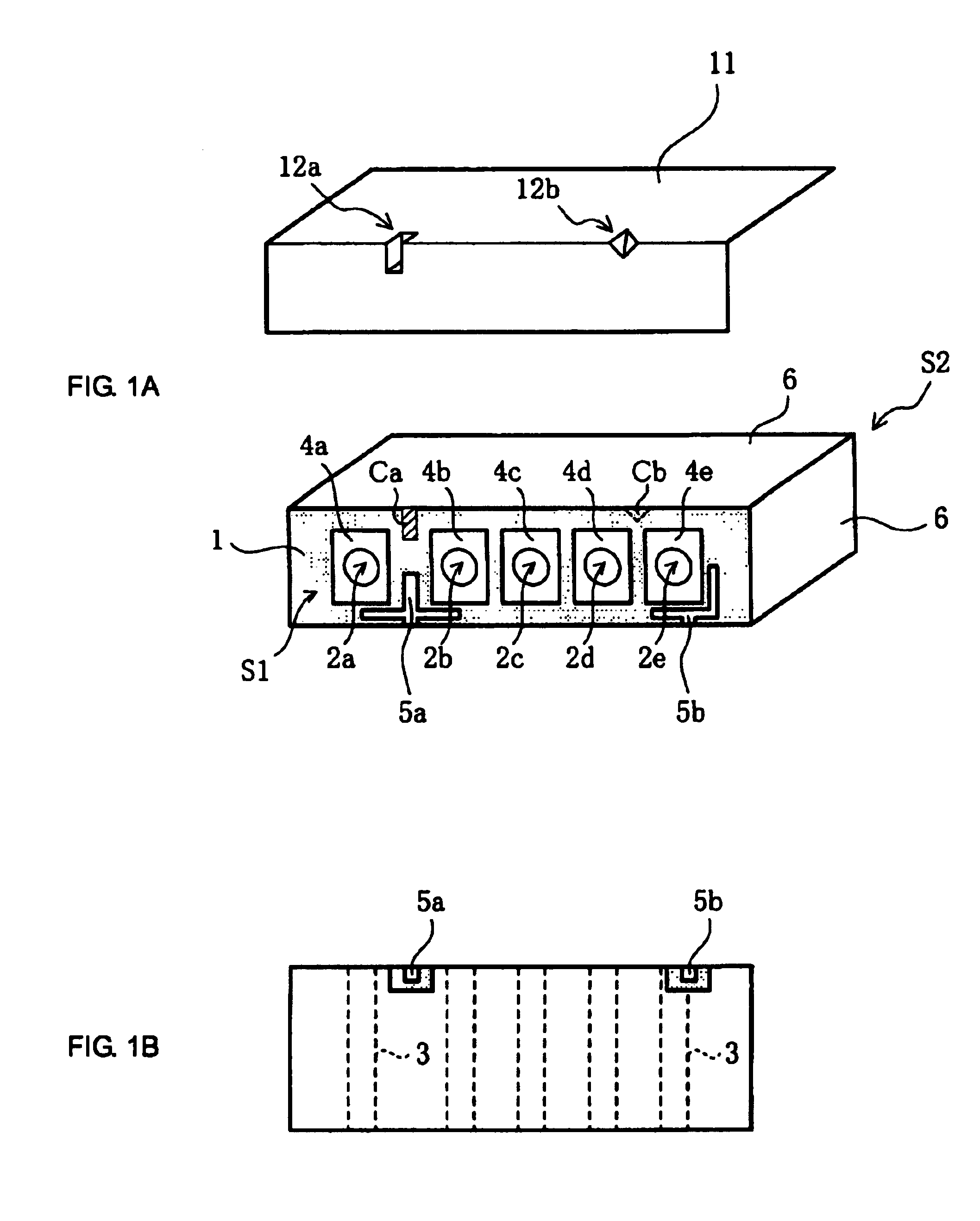
[0024]FIG. 1A is an exploded perspective view of the dielectric filter, and FIG. 1B is a bottom view of the dielectric filter. The dielectric block 1 is preferably a substantially rectangular parallelepiped. Between a first surface S1 (hereinafter also referred to as the “open circuit surface”) of the dielectric block 1 and a second surface S2 opposite thereto, five resonator holes 2a to 2e are arranged in parallel. On the internal surfaces of the resonator holes 2a to 2e, internal conductors 3 are formed. Among the external surfaces (six surfaces) of the dielectric block 1, preferably five surfaces other than the open circuit surface S1 have external conductors 6 formed thereon. The internal conductors 3 on the internal surfaces of the resonator holes 2a to 2e are conductively coupled with the external conductors 6 on the second surface S2 of the dielect...

second embodiment

[0031]Next, a dielectric duplexer according to the present invention is described below with reference to FIGS. 3A to 4.

[0032]FIG. 3A is an exploded perspective view of the dielectric duplexer, and FIG. 3B is a bottom view of the dielectric duplexer. The dielectric block 1, preferably a substantially rectangular parallelepiped, is shown with seven resonator holes 2a to 2g extending between a first surface (hereinafter also referred to as an “open circuit surface”) S1 and a second surface S2 opposite thereto. The resonator holes 2a to 2g have internal conductors formed on their internal surfaces. Among the external surfaces (six surfaces) of the dielectric block 1, preferably five surfaces other than an open circuit surface S1 have external conductors 6 formed thereon. The internal conductors on the internal surfaces of the resonator holes 2a to 2g are conductively coupled with the external conductors 6 on the second surface S2 of the dielectric block 1. In other words, the second su...

third embodiment

[0037]Next, a communication apparatus according to the present invention is described below with reference to FIG. 5.

[0038]The communication apparatus preferably includes a transmitting / receiving antenna ANT, a duplexer DPX, bandpass filters BPFa and BPFb, amplifying circuits AMPa and AMPb, mixers MIXa and MIXb, an oscillator OSC, and a frequency synthesizer SYN.

[0039]The mixer MIXa mixes a transmitting intermediate frequency IF and a signal output from the frequency synthesizer SYN. The bandpass filter BPFa only allows a transmitting frequency band in a mixed signal output from the mixer MIXa to pass through it. The amplifying circuit AMPa performs power amplification on the transmitting frequency band and transmits the amplified signal from the antenna ANT. The amplifying circuit AMPb amplifies a received signal extracted from the duplexer DPX. The bandpass filter BPFb allows only a received frequency band in the received signal output from the amplifying circuit AMPb to pass thro...


PUM


Abstract

A dielectric filter includes a conductive cover formed by bending a metal plate and forming at least one inwardly projecting portion at a predetermined position along the bent portion. The inner surface of the at least one inwardly projecting portion abuts on an open circuit surface or edge of a dielectric block. Thus, the distance between the open circuit surface of the filter and the conductive cover is reliably maintained and unnecessary coupling between adjacent resonators is prevented.

Description

BACKGROUND OF THE INVENTION[0001]1. Field of the Invention[0002]The present invention relates to a dielectric filter provided with a dielectric block and a conductive cover, a dielectric duplexer, and a communication apparatus including the dielectric filter and the dielectric duplexer.[0003]2. Description of the Related Art[0004]A dielectric filter which has a substantially-rectangular-parallelepiped dielectric block having resonator holes arranged in parallel and internal conductors formed on internal surfaces of the resonator holes, and which has external conductors formed on the filter has been used as a microwave filter.[0005]In the dielectric filter of the above type, in order to eliminate a problem of unnecessary radiation of electromagnetic waves from an open circuit surface of the dielectric filter to the exterior, or unnecessary coupling with the exterior, a conductive cover is provided to cover the open circuit surface of the dielectric block (e.g., Japanese Unexamined Pa...

Claims


Application Information

Patent Timeline
Patent Type & Authority Patents(United States)
IPC IPC(8): H01P1/213H01P1/20H01P1/205
CPCH01P1/2056H01P1/2136
Inventor KITAICHI, YUKIHIROMARUYAMA, TAKASHIYAMADA, YASUO
Owner MURATA MFG CO LTD
Why Eureka
Try Eureka