Telescopic boom and mobile crane

a technology of telescopic boom and crane, which is applied in the direction of cranes, transportation and packaging, etc., can solve the problems of high risk of buckling, high weight of the total structure, and sheet metal structure, and achieve the effect of saving weight, optimizing force flow, and increasing load weigh

Active Publication Date: 2019-12-03
LIEBHERR WERK EHINGEN
View PDF8 Cites 0 Cited by
  • Summary
  • Abstract
  • Description
  • Claims
  • Application Information

AI Technical Summary

Benefits of technology

[0008]A new structure for the connection of the luffing cylinder to the boom section is therefore looked for that permits an optimized force flow from the luffing

Problems solved by technology

The disadvantage of this sheet metal structure can be illustrated using FIG. 2 that schematically shows the force flow from the luffing cylinder into the boom section during the crane work.
However, this has a plurality of disadvantages:The force flows through a large buckling field C that is not stiffened.
The high sheet metal thickness of the top metal sheet 3 therefore required results in a high weight of the total structure.A high risk of buckling arises due to the portion of the compressive force (pressure seam/tension seam b) in the soft sect

Method used


Image

  • Telescopic boom and mobile crane
  • Telescopic boom and mobile crane
  • Telescopic boom and mobile crane

Examples


Embodiment Construction

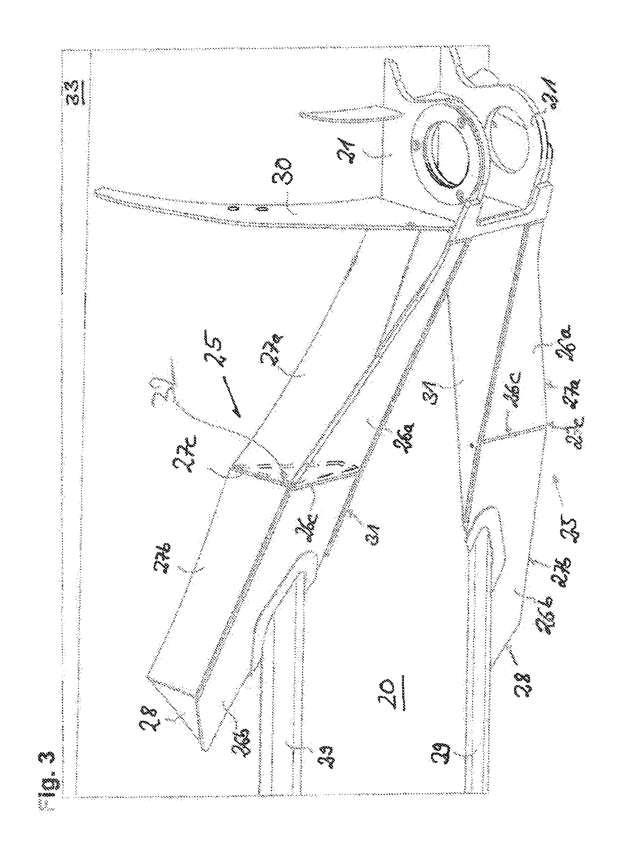
[0029]FIGS. 3 and 4 now show the innovative structure of the telescopic boom system. A part region of the lower shell 20 of the telescopic boom can be seen that has the bolt mount for the connection of the luffing cylinder. The two bolt metal support sheets 21 are provided with respective reinforcement metal sheets for the mounting of bolt of the luffing cylinder. Two narrow, closed sheet metal boxes 25 adjoin them and are designed identically with one another. Both boxes 25 each comprise a two-part top metal sheet having the individual elements 26a, 26b that are connected to one another in the edge 26c. The two outer side walls of the sheet metal box structures 25 are also designed in two parts having the individual elements 27a, 27b that meet one another in the edge 27c. A terminal metal sheet 28 is provided at the front-side end. The inner side walls 31 of the sheet metal box structures are designed in one piece.

[0030]A respective inner standing metal sheet 32 (only drawn once) i...


PUM


Abstract

The present invention relates to a telescopic boom having a coupling section at whose lower shell at least one luffing cylinder mount, in particular a bolt mount, is centrally provided for fastening at least one luffing cylinder, wherein at least two closed sheet metal box structures for the load transmission from the luffing cylinder mount into the structure of the telescopic boom are provided at the support metal sheets of the luffing cylinder mount.

Description

BACKGROUND OF THE INVENTION[0001]The invention relates to a telescopic boom for a crane, in particular for a mobile crane, at whose lower shell at least one luffing cylinder mount, in particular a bolt mount is centrally provided for fastening at least one luffing cylinder.[0002]A plurality of crane models use a centrally arranged luffing cylinder that can be bolted to the coupling section of the telescopic boom via a bolt mount. The load transmission thus takes place via the bolt mount into the lower shell of the boom section, which makes a special sheet metal structure of the bolt support necessary. The illustration of FIG. 1 shows a conventional solution of the luffing cylinder mount of the prior art. The two bolt metal support sheets 2 are shown that are welded to the lower shell 7 of the coupling section 1. A comparatively wide and closed sheet metal structure 4 adjoins the supporting metal sheets 2 and consists of a top metal sheet 3 and two sides walls divided into two and ha...

Claims


Application Information

Patent Timeline
IPC IPC(8): B66C23/70
CPCB66C23/701B66C2700/0357B66C23/82B66C23/64
Inventor BRZOSKA, SEBASTIANHELBIG, MARIO
Owner LIEBHERR WERK EHINGEN
Why Eureka
Try Eureka