Self-righting remotely controlled object

a remote controlled object and self-righting technology, applied in the field of flying toys, can solve the problems of not being able to use in catapulting targeting systems, flying toys are difficult to control, and known flying toys cannot right and stabilize themselves, so as to prevent or reduce damage from ceiling impacts

Active Publication Date: 2019-12-10
GOLLIHER CLAYTON R
View PDF8 Cites 0 Cited by
  • Summary
  • Abstract
  • Description
  • Claims
  • Application Information

AI Technical Summary

Benefits of technology

[0005]The present invention addresses the above and other needs by providing a self-righting flier which includes a battery residing at a rounded bottom of a flier body, propeller blades, and louvers below the propeller blades. The louvers include rounded projections extending down the bottom most corners. The bottom location of the battery and the louvers provide the self-righting of the flier. The flier further includes a top most guard preventing or reducing damage from ceiling impacts.
[0007]In accordance with another aspect of the invention, there is provided a flier including louvers which stabilize the flier. The louvers are located below propellers and direct air downward to help keep the flier vertical, as well as stabilize its motion. The louvers include rounded bottoms which provide the self-righting feature.
[0008]In accordance with yet another aspect of the invention, there is provided a flier having batteries in the bottom of a flier body. The battery location adds stability to the flier and also helps cause it to rig ht itself.
[0009]In accordance with still another aspect of the invention, there is provided a flier having a ceiling guard above the propellers for prevent damage to the flier and ceiling and prevent vacuum created by the propeller from holding the flier against the ceiling. The ceiling guard may be “U” shaped made from rubber, foam, cloth, etc.

Problems solved by technology

Known one channel flying toys are hard to control.
Known flying toys cannot right and stabilize themselves if thrown or catapulted into midair.
So they cannot be used in a catapulting targeting system.
Known flying toys may fall in any position, and be damaged or have to be manually placed in an upright position before launching.
Other flying toys cannot be thrown up in the air because they will not auto stabilize themselves and will crash.
Other one channel fliers will stick to the ceiling and cannot be easily controlled and will tend to crash to the floor.

Method used


Image

  • Self-righting remotely controlled object
  • Self-righting remotely controlled object
  • Self-righting remotely controlled object

Examples


Embodiment Construction

[0022]The following description is of the best mode presently contemplated for carrying out the invention. This description is not to be taken in a limiting sense, but is made merely for the purpose of describing one or more preferred embodiments of the invention. The scope of the invention should be determined with reference to the claims.

[0023]Where the terms “about” or “generally” are associated with an element of the invention, it is intended to describe a feature's appearance to the human eye or human perception, or to within 5 percent for lengths, and not a precise measurement.

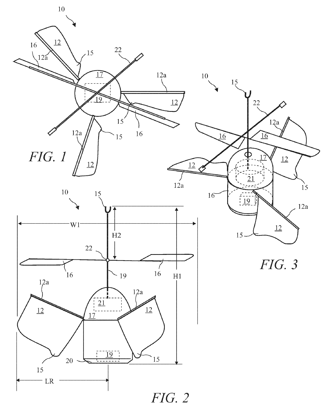
[0024]A top view of a flier 10 according to the present invention is shown in FIG. 1, a side view of the flier 10 is shown in FIG. 2, and a top and side view of the flier 10 is shown in FIG. 3. The flier 10 includes a body 17 containing a battery 19 residing at the bottom 20 of the body 17 and a motor 21 residing above the battery 19. The bottom 20 assisting in self-righting the flier 10 and is preferabl...


PUM


Abstract

A self-righting flier includes a battery residing at a rounded bottom of a flier body, propellor blades and louvers below the propellor blades. The louvers include rounded projections extending down of bottom most corners. The bottom location of the battery and the louvers provide the self-righting of the flier. The flier further includes a top most guard preventing or reducing damage from ceiling impacts.

Description

CROSS-REFERENCE TO RELATED APPLICATIONS[0001]The present application claims the priority of U.S. Provisional Patent Application Ser. No. 62 / 531,625 filed Jul. 12, 2017, which application is incorporated in its entirety herein by reference.BACKGROUND OF THE INVENTION[0002]The present invention relates to flying toys, and in particular to a self-righting break resistant flying toy.[0003]Known one channel flying toys are hard to control. Known flying toys cannot right and stabilize themselves if thrown or catapulted into midair. So they cannot be used in a catapulting targeting system.[0004]Known flying toys may fall in any position, and be damaged or have to be manually placed in an upright position before launching. Other flying toys cannot be thrown up in the air because they will not auto stabilize themselves and will crash. Other one channel fliers will stick to the ceiling and cannot be easily controlled and will tend to crash to the floor.BRIEF SUMMARY OF THE INVENTION[0005]The ...

Claims


Application Information

Patent Timeline
Patent Type & Authority Patents(United States)
IPC IPC(8): A63H27/00G05D1/08G05D1/10A63H15/06G05D1/00A63H29/22A63H30/04
CPCA63H30/04A63H27/12A63H29/22A63H15/06G05D1/0816B64C2203/00G05D1/0011G05D1/101
Inventor GOLLIHER, CLAYTON R.
Owner GOLLIHER CLAYTON R
Why Eureka
Try Eureka