
Control system for vehicle

a control system and vehicle technology, applied in the direction of gearing control, gearing elements, belts/chains/gearrings, etc., can solve the problem of torque drop (driving force) against the driver's body

Active Publication Date: 2019-12-17
TOYOTA JIDOSHA KK
View PDF19 Cites 0 Cited by
  • Summary
  • Abstract
  • Description
  • Claims
  • Application Information

AI Technical Summary

Benefits of technology

The invention is a control system for a vehicle that can prevent a drop in torque when switching from one gear to another in the automatic transmission. This is accomplished by keeping the shift range in the neutral position for a set amount of time, so that it doesn't change when the user repeatedly presses the same button. This prevents any unnatural or sudden drop in power when shifting gears, resulting in a better driving experience. Additionally, the system can also detect if the user is trying to shift to a specific position and will move the shifter accordingly.

Problems solved by technology

Therefore, depending on the length of the predetermined time, there is a possibility that a torque (driving force) drop occurs against a driver's intention because of the temporarily set neutral range although the operator is intended to be operated to the other operation position.

Method used


Image

  • Control system for vehicle
  • Control system for vehicle
  • Control system for vehicle

Examples


Embodiment Construction

[0028]Hereinafter, an embodiment of the invention will be described in detail with reference to the accompanying drawings.

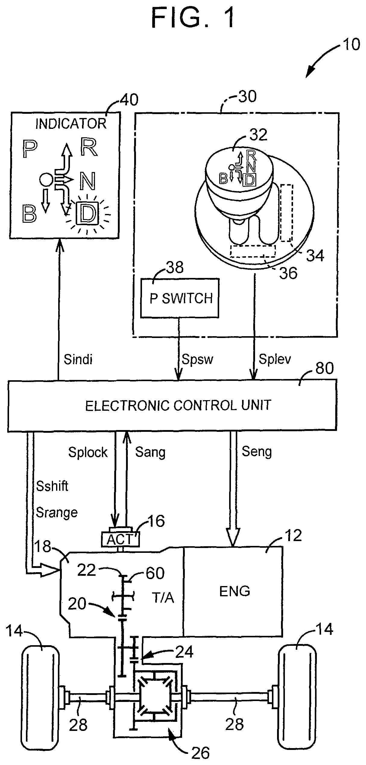
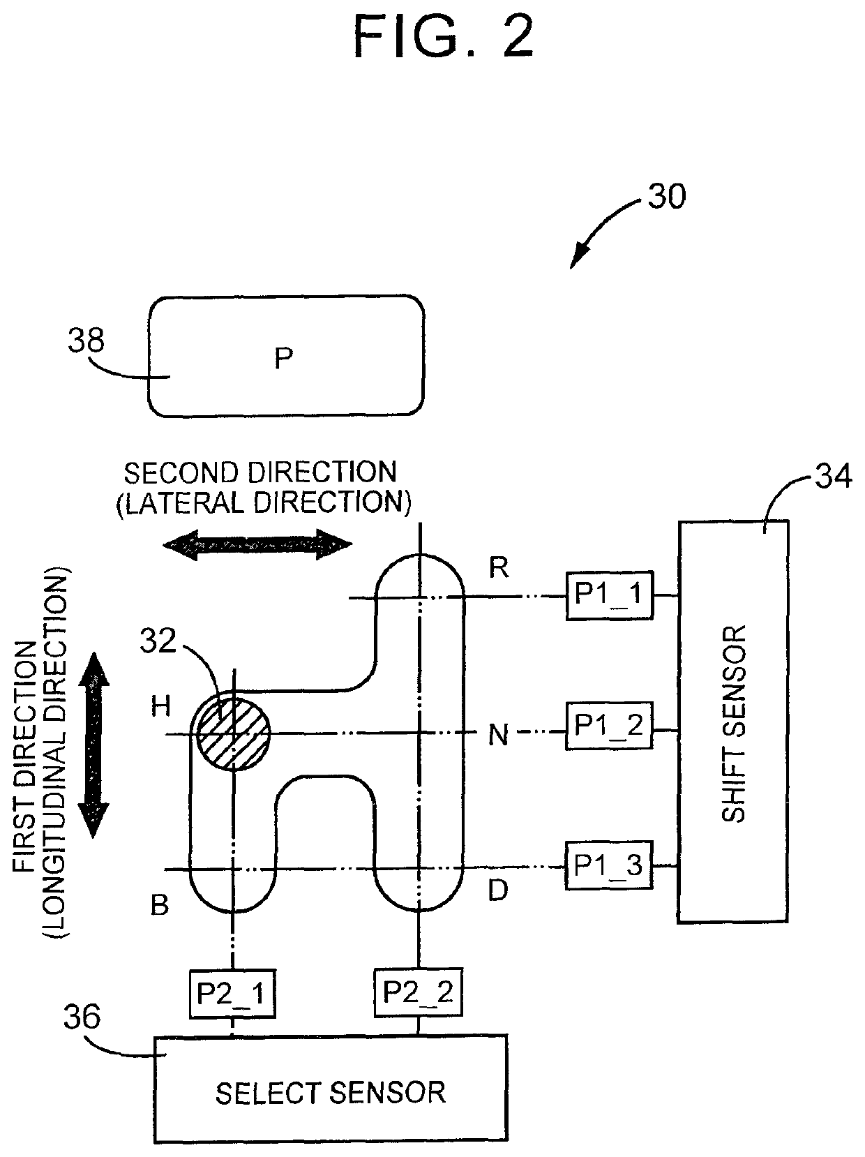
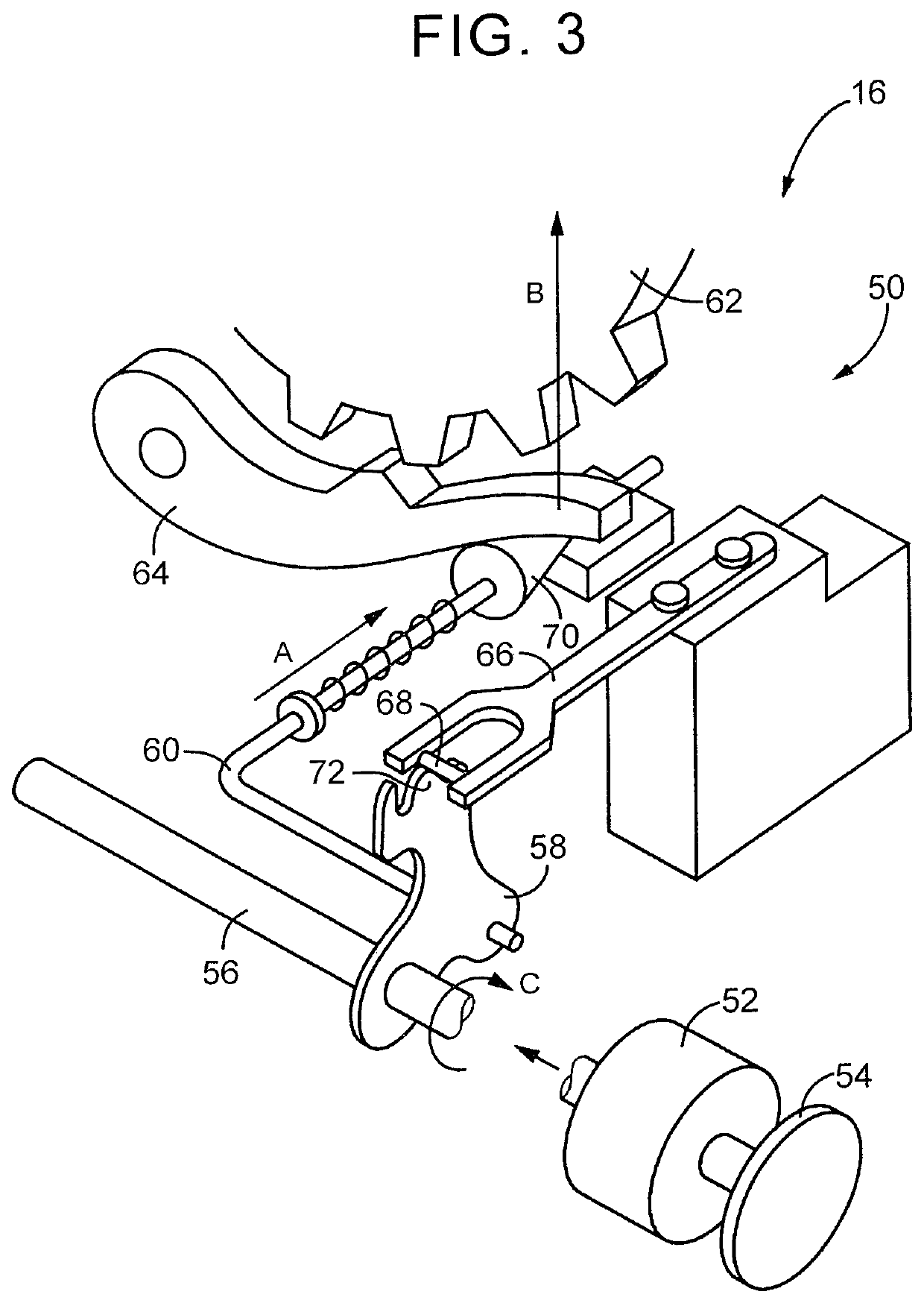
[0029]FIG. 1 is a view that illustrates the schematic configuration of a power transmission path from an engine 12 to drive wheels 14, which constitute a vehicle 10 to which the invention is applied. FIG. 1 is a block diagram that illustrates a relevant portion of a control system provided in the vehicle 10 in order to control a change mechanism 16, and the like. As shown in FIG. 1, the vehicle 10 includes the change mechanism 16, an automatic transmission 18, and the like. The vehicle 10 employs a shift-by-wire (SBW) system in which a shift range (shift position) of the automatic transmission 18 is changed through electric control. The automatic transmission 18, for example, transmits the power of the engine 12 from an output gear 22 to the pair of drive wheels 14 sequentially via a counter gear pair 20, a final gear pair 24, a differential gear 26, a pair of dr...


PUM


Abstract

An operator is a momentary operator. An electronic control unit is configured to when the operator does not pass through any one of traveling operation positions while the operator is operated from an initial position to an neutral operation position and then returned to the initial position, and when the operator is continuously held at the neutral operation position for a first predetermined time or longer, change a shift range of an automatic transmission to the neutral range, and when the operator passes through at least one of the traveling operation positions while the operator is operated from the initial position to the neutral operation position and then returned to the initial position, prohibit a change of the shift range to the neutral range even when the operator is continuously held at the neutral operation position for the first predetermined time or longer.

Description

BACKGROUND OF THE INVENTION1. Field of the Invention[0001]The invention relates to a control system for a vehicle, which electrically changes a shift range of an automatic transmission on the basis of an operation position in a momentary-type operation device.2. Description of Related Art[0002]There is well known a vehicle that employs a shift-by-wire (SBW) system. The shift-by-wire (SBW) system means a system of electrically changing a shift range of an automatic transmission on the basis of an operation position of an operator (for example, a shift lever or a switch) in an operation device that is artificially operated. In such a vehicle that employs the SBW system, a momentary-type operator may be used as the operator in the operation device. The momentary-type operator is returned to an initial position in a state where no external force is applied. Such an operation device is, for example, the SBW-system operation device described in Japanese Patent Application Publication No. ...

Claims


Application Information

Patent Timeline
Patent Type & Authority Patents(United States)
IPC IPC(8): F16H59/10F16H61/16F16H59/02
CPCF16H59/105F16H59/0204F16H61/16F16H2059/0295F16H61/0213F16H61/0248
Inventor SHINE, KAZUMINAKADE, YUSUKEUEJIMA, TAIYOSHIBATA, HIROSHI
Owner TOYOTA JIDOSHA KK
Learn More