
Compressor motor and compressor

A technology for compressors and motors, applied in the field of compressors, can solve the problems of motor torque reduction, cost increase, and increase in winding amount, etc. Effect

Active Publication Date: 2011-05-18
DAIKIN IND LTD
View PDF1 Cites 0 Cited by
  • Summary
  • Abstract
  • Description
  • Claims
  • Application Information

AI Technical Summary

Problems solved by technology

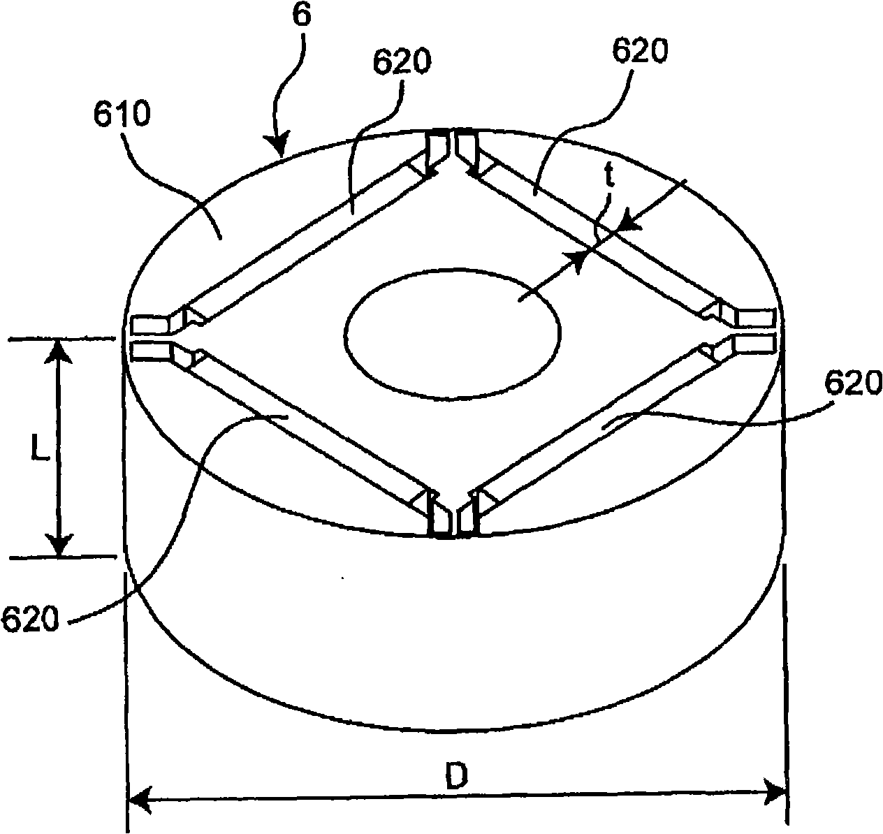
That is, in the case of L / D<0.7, if the axial length L of the rotor core is shortened to shorten the axial length of the rotor, the leakage of magnetic flux from both end surfaces of the rotor increases, and the torque of the motor increases. decline
[0008] In addition, for example, for efficiency reduction, as in the above-mentioned document (Japanese Patent Application Laid-Open No. 9-191588 (Patent No. 3017085)), there is a method of increasing the space factor of the above-mentioned coil to improve the efficiency of the motor, but it is impossible to prevent the loss of torque. decline
In addition, there is also a disadvantage that the amount of winding of the above-mentioned coil increases and the cost increases.

Method used


Image

  • Compressor motor and compressor
  • Compressor motor and compressor
  • Compressor motor and compressor

Examples


Embodiment Construction

[0030] Hereinafter, the present invention will be described in detail based on the illustrated embodiments.

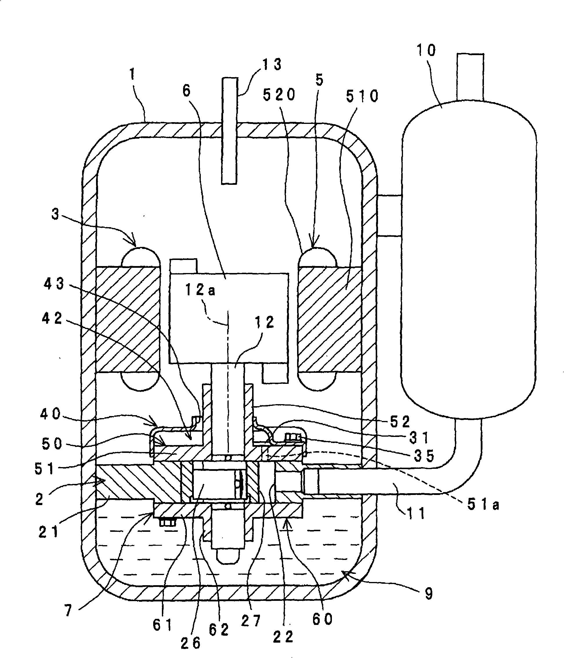
[0031] figure 1 A longitudinal sectional view showing one embodiment of the compressor of the present invention. This compressor includes: an airtight container 1 ; a compression unit 2 arranged in the airtight container 1 ; and a motor 3 arranged in the airtight container 1 and driving the compression unit 2 via a shaft 12 .

[0032] This compressor is a so-called vertical high-pressure dome type rotary compressor, and the compression unit 2 is arranged below and the electric motor 3 is arranged above in the airtight container 1 . The compression unit 2 is driven by the rotor 6 of the electric motor 3 via the shaft 12 .

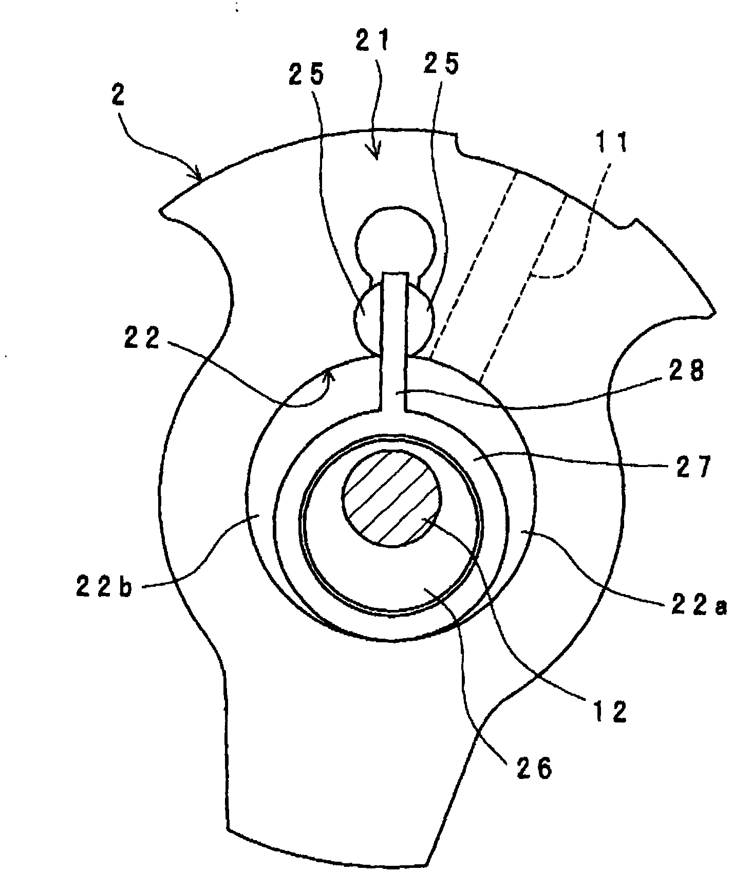
[0033] The compression unit 2 sucks refrigerant gas from the accumulator 10 through the suction pipe 11 . The refrigerant gas is obtained by controlling an unillustrated condenser, expansion mechanism, and evaporator constituting an air conditione...


PUM


Abstract

A rotor 6 includes a rotor core 610, and a plurality of magnets 620 arrayed on the rotor core 610 in its circumferential direction at center angles of equal intervals. Given an axial length L of the rotor core 610, a radial length D of the rotor core 610, and a thickness t of the magnets 620, the following relationships are satisfied: L / D < 0.7, and t > (1K) / (L 1.5 DP) (wherein P is the number ofpoles, K is 100000, and N is a factor that depends on the output of the compressor). Thus, while torque decreases due to large reduction in rotor layering thickness is suppressed, a small-size, lightweight and low-priced compressor motor is provided.

Description

technical field [0001] The present invention relates to, for example, a motor for a compressor used in an air conditioner or a refrigerator, and a compressor including the motor for a compressor. Background technique [0002] Conventionally, a compressor has: an airtight container; a compression unit arranged in the airtight container; and a motor arranged in the airtight container and driving the compression unit via a shaft. The motor described above has a rotor and a stator arranged radially outside of the rotor. [0003] The rotor has a rotor core and a plurality of magnets arranged at equal intervals in the circumferential direction of the rotor core. The stator has a stator core and a coil wound around the stator core (see Japanese Patent Application Laid-Open No. 9-191588 (Japanese Patent No. 3017085)). [0004] However, in the conventional compressor described above, if the axial length of the electric motor is shortened in order to reduce the size and weight of th...

Claims


Application Information

Patent Timeline
Patent Type & Authority Patents(China)
IPC IPC(8): H02K1/27F04B39/00H02K21/14
CPCH02K1/276F04C18/322F04C29/0085F04B35/04F04C23/008
Inventor 片冈义博青田桂治中增伸
Owner DAIKIN IND LTD
Learn More