
Drive unit and motor system for brushless DC motors

a technology of dc motors and drive units, which is applied in the direction of electronic commutator control, electronic commutator control, control systems, etc., can solve the problems of torque drop, noise and vibration at a low rotation number, torque drop, etc., and achieve the effect of suppressing noise and vibration and suppressing torque drop

Active Publication Date: 2021-07-06
MABUCHI MOTOR
View PDF3 Cites 0 Cited by
  • Summary
  • Abstract
  • Description
  • Claims
  • Application Information

AI Technical Summary

Benefits of technology

This approach effectively suppresses noise and vibration while maintaining torque by setting suitable voltage values for each phase, improving output efficiency and reducing torque drop at low rotation numbers compared to rectangular wave energization.

Problems solved by technology

However, in a brushless DC motor adopting a hall element, the energization timing deviates (becomes late or early) when the rotation number is low such as a starting time.
As a result, the torque drops.
However, in the typical drive unit for brushless DC motors, noise and vibration become large at a low rotation number (at the time of rectangular wave energization drive).

Method used


Image

  • Drive unit and motor system for brushless DC motors
  • Drive unit and motor system for brushless DC motors
  • Drive unit and motor system for brushless DC motors

Examples


Embodiment Construction

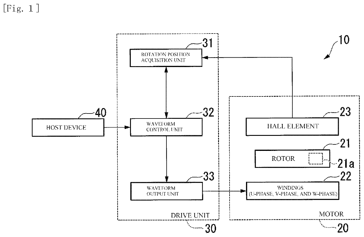
[0026]Hereinafter, a motor system 10 according to an embodiment of the present disclosure will be described with reference to the drawings.

[0027]As shown in FIG. 1, the motor system 10 includes a brushless DC motor 20 (hereinafter, referred to as a motor 20) and a drive unit 30 for the motor 20. The motor system 10 may have a configuration in which the motor 20 and the drive unit 30 are integrated (so-called an intelligent motor) or a configuration in which the motor 20 and the drive unit 30 are not integrated.

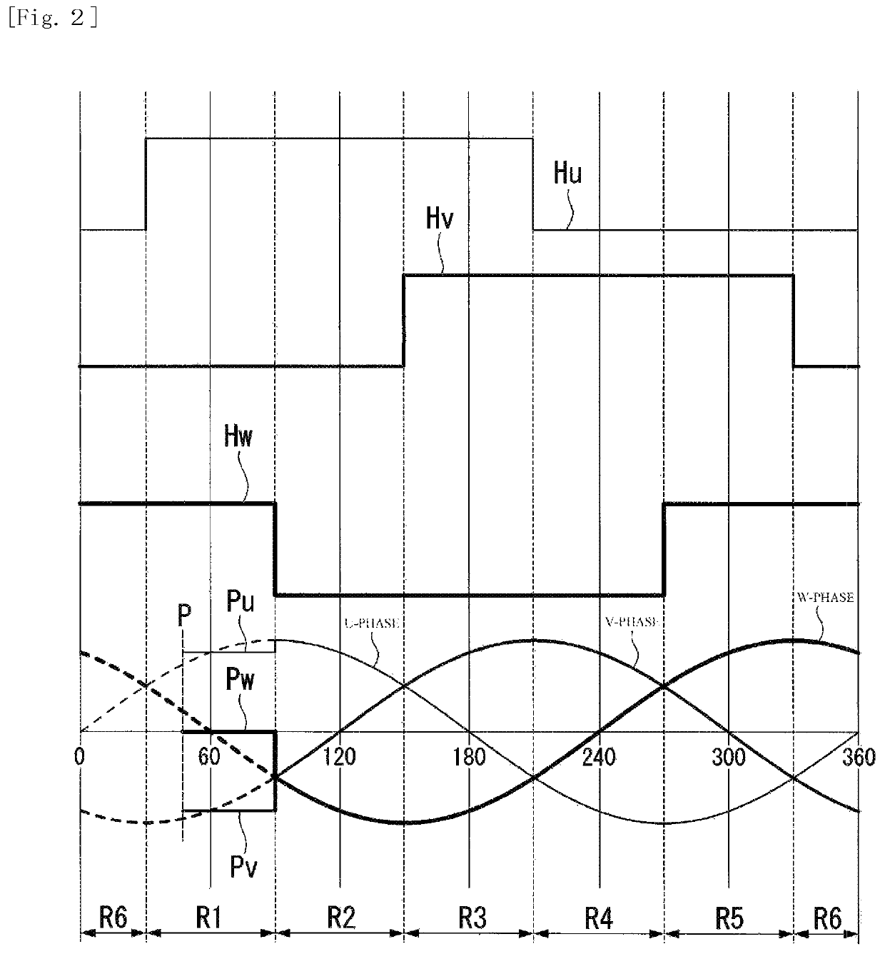
[0028]The motor 20 includes a rotor 21, n-phase (n is a natural number of two or more) windings 22 (coil) that face the rotor 21 in a radial direction and rotate the rotor 21, and a hall element 23 (element) that detects the rotation position of a rotation reference 21a provided on the rotor 21 at an interval of a predetermined electrical angle θR.

[0029]The rotor 21 has two magnetic poles. In the motor 20, the mechanical angle and the electrical angle coincide with each other....


PUM


Abstract

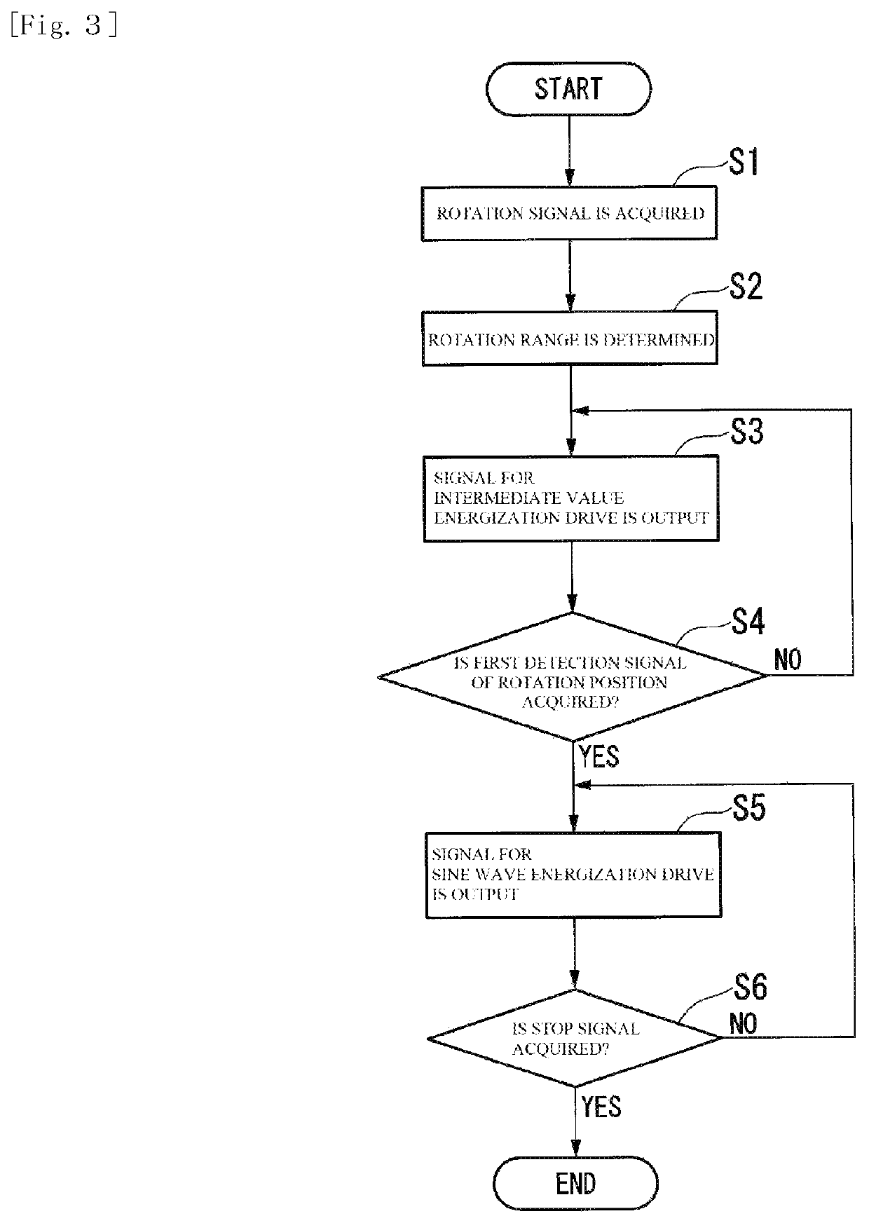
A waveform control unit outputs a signal for driving a brushless DC motor by intermediate value energization to a waveform output unit, and outputs a signal for driving a brushless DC motor by sine wave energization to the waveform output unit when the signal in which the rotation position of the rotation reference is detected is acquired from the element, and the waveform control unit applies voltage corresponding to a sine value of an angle of a winding of one phase of n-phase windings when the brushless DC motor is to be driven by intermediate value energization, and outputs a signal for applying voltage corresponding to a sine value of an angle having similar phase difference as the sine wave energization drive with respect to the angle to the rest of the windings.

Description

CROSS-REFERENCE TO THE RELATED APPLICATION[0001]This application claims priority to Japanese Patent Application No. 2019-038808, filed Mar. 4, 2019, the entire contents of which is incorporated herein by reference.BACKGROUNDTechnical Field[0002]The present disclosure relates to a drive unit and a motor system for brushless DC motors.Related Art[0003]As a method of driving a brushless DC motor, sine wave energization drive is known. The sine wave energization drive has higher efficiency compared with rectangular wave energization drive.[0004]A hall element is adopted as a position detection element of a rotor in a brushless DC motor. By adopting a hall element, the cost of the brushless DC motor can be reduced.[0005]However, in a brushless DC motor adopting a hall element, the energization timing deviates (becomes late or early) when the rotation number is low such as a starting time. As a result, the torque drops.[0006]In order to address the above issue, a brushless DC motor drive ...

Claims


Application Information

Patent Timeline
Patent Type & Authority Patents(United States)
IPC IPC(8): H02P6/15
CPCH02P6/153H02P6/10H02P6/20H02P6/16H02P2203/03
Inventor FUJII, SHUNPEI
Owner MABUCHI MOTOR
Learn More