System and method for discriminating between origins of vibrations in an object and determination of contact between blunt bodies traveling in a medium

a technology of origin and object, applied in the field of vibration analysis, can solve the problems of contacting objects being required to enter and remain, image to be resolved, and engine death, and achieve the effects of reducing false positives, reducing cost and intrusion of detection equipment, and improving accuracy

Active Publication Date: 2019-12-17
MASSACHUSETTS INST OF TECH
View PDF6 Cites 0 Cited by
  • Summary
  • Abstract
  • Description
  • Claims
  • Application Information

AI Technical Summary

Benefits of technology

[0008]This invention overcomes disadvantages of the prior art by providing a system and a method for discriminating between contact of bodies travelling in a medium and pressure waves of the medium interacting with the bodies. This system and method improves accuracy and reduces false positives in the determination of contact between objects, while reducing the cost and intrusiveness of detection equipment.

Problems solved by technology

For instance, turbine blades spinning at high speed in a nacelle will deteriorate and possible cause fatal destruction of the engine if they come in contact with the nacelle.
This method has the disadvantage of the contacted objects being required to enter and remain in the observable plane of the camera for a sufficiently long time for the image to be resolved.
Therefore this method requires a number of very expensive cameras in order to be effective.
Also, as has been showed recently, there exists a condition where this method can create a false positive.
Vibration detection mechanisms have been suggested but have not been implemented on a wide range of equipment.
Often these alterations are intrusive to the equipment, require mobile power sources, and require additional signal conditioning electronics.
This method is also highly susceptible to false positives when objects are close to, but not touching each other.

Method used


Image

  • System and method for discriminating between origins of vibrations in an object and determination of contact between blunt bodies traveling in a medium
  • System and method for discriminating between origins of vibrations in an object and determination of contact between blunt bodies traveling in a medium
  • System and method for discriminating between origins of vibrations in an object and determination of contact between blunt bodies traveling in a medium

Examples


Embodiment Construction

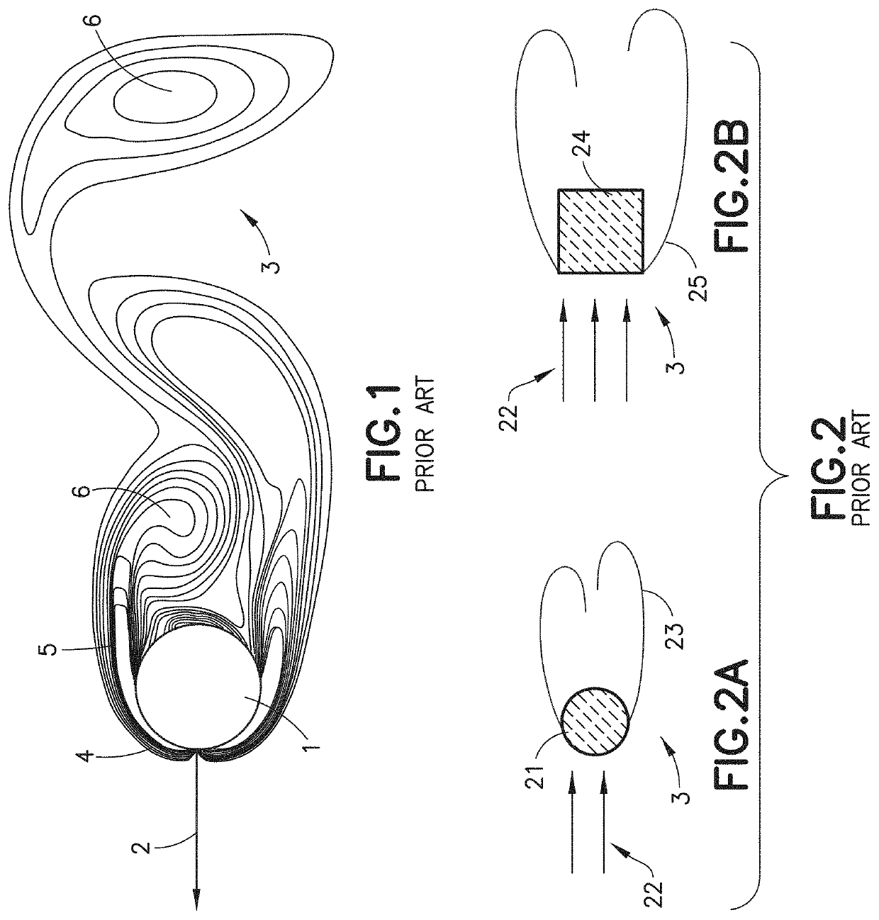
[0026]When an object travels through a medium such as air, the object creates pressure waves within the medium. These pressure waves are of different types, shapes, and forms based on the geometry and speed of the object as shown in FIG. 1. Here object 1 is a sphere viewed in two dimensions. The flow lines are also shown in two dimensions per illustration, but exist all around the sphere, as is known to those of ordinary skill in the art. As object 1 moves in direction 2 through medium 3, compression waves 4 are formed in front of object 1. These compression waves force flow around body 1 creating compression and expansion waves 5 in the medium. As is known by those having ordinary skill in the art, compression waves and expansion waves are types of pressure waveforms. The net result is wake 6, which is a series of compression and expansion waves that exists in medium 3 for a while after object 1 has moved through. The intensity and duration of wake 6 is dependent on the velocity, s...


PUM


Abstract

A system and method for accurately detecting contact between two objects in a medium comprises at least one sensor for detecting vibration of a first of the two objects and a central processing unit (CPU) for receiving an output of the at least one sensor, wherein the CPU performs the steps: converting the output of the sensor into digital form; during a calibration phase, changing the data from time domain to frequency domain; and during the calibration phase, determining a first frequency range associated with actual contact between the two objects, and a second frequency range associated with a false positive contact between the two objects. A signal processor is provided for filtering all data except that which falls within the first frequency range so as to confirm actual contact between the objects.

Description

CROSS-REFERENCE TO RELATED APPLICATIONS[0001]This application claims the benefit of U.S. Provisional Patent Application Ser. No. 62 / 250,495, filed Nov. 3, 2015, entitled “SYSTEM AND METHOD FOR DISCRIMINATING BETWEEN ORIGINS OF VIBRATIONS IN AN OBJECT AND DETERMINATION OF CONTACT BETWEEN BLUNT BODIES TRAVELING IN A MEDIUM”, which is incorporated by reference herein in its entirety.FIELD OF THE INVENTION[0002]This invention relates to analysis of vibrations through an object or a medium the object travels through.BACKGROUND OF THE INVENTION[0003]There are many applications where it is desired to know if and when two objects travelling in a medium have touched or not. For instance, turbine blades spinning at high speed in a nacelle will deteriorate and possible cause fatal destruction of the engine if they come in contact with the nacelle. In the game of cricket, the bat and ball are in an air medium and contact between the two objects determines fate of a batsmen. Similarly, in the ga...

Claims


Application Information

Patent Timeline
Patent Type & Authority Patents(United States)
IPC IPC(8): G01V1/00
CPCG01V1/001
Inventor PRETORIUS, JACOBSARMA, SANJAYHO, STEPHEN SAI-WUNG
Owner MASSACHUSETTS INST OF TECH
Why Eureka
Try Eureka