Photorefractive flash device and system

a technology of photorefractive flash and flash device, which is applied in the field of photorefractive flash device and method, can solve the problems of not only being able to calculate the spheric error of the ey

Active Publication Date: 2020-01-14
REIS ALEXANDER +3
View PDF1 Cites 1 Cited by
  • Summary
  • Abstract
  • Description
  • Claims
  • Application Information

AI Technical Summary

Benefits of technology

[0013]The current invention is a Photorefractive Flash Device and System. It is a device to illuminate the pupil in a way, that allows a proper pupillary reflex. By analyzing this reflex a user can calculate the refractive error of an eye.

Problems solved by technology

By positioning the LEDs in this way, it is not only possible to calculate the spheric error of an eye (myopia and hyperopia).

Method used


Image

  • Photorefractive flash device and system
  • Photorefractive flash device and system
  • Photorefractive flash device and system

Examples


Embodiment Construction

[0024]There are a number of significant design features and improvements incorporated within the invention. The current invention is a Photorefractive Flash Device and System.

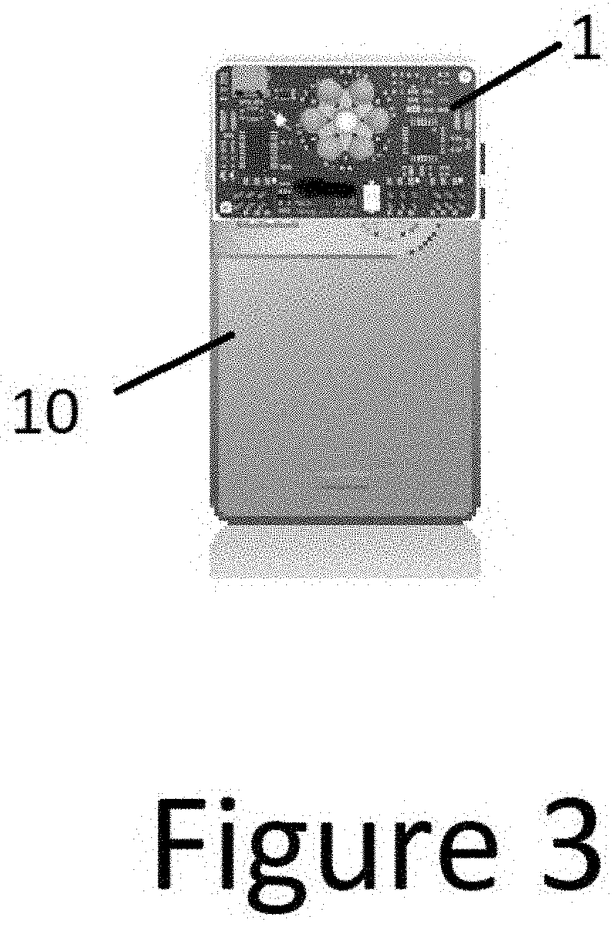
[0025]While Photorefraction was invented in the 1970s, and is a method to measure the refraction of an eye by analyzing the pupils red reflex using a photograph of the pupil, prior to the current invention there were only two devices using this method. Both are handheld and expensive and are infrared base. The current invention is a device and method to transfer this principle to any handheld-device 10, such as a smartphone, tablet or laptop computer. This method can be used with any device with a camera and a microprocessor or web connection.

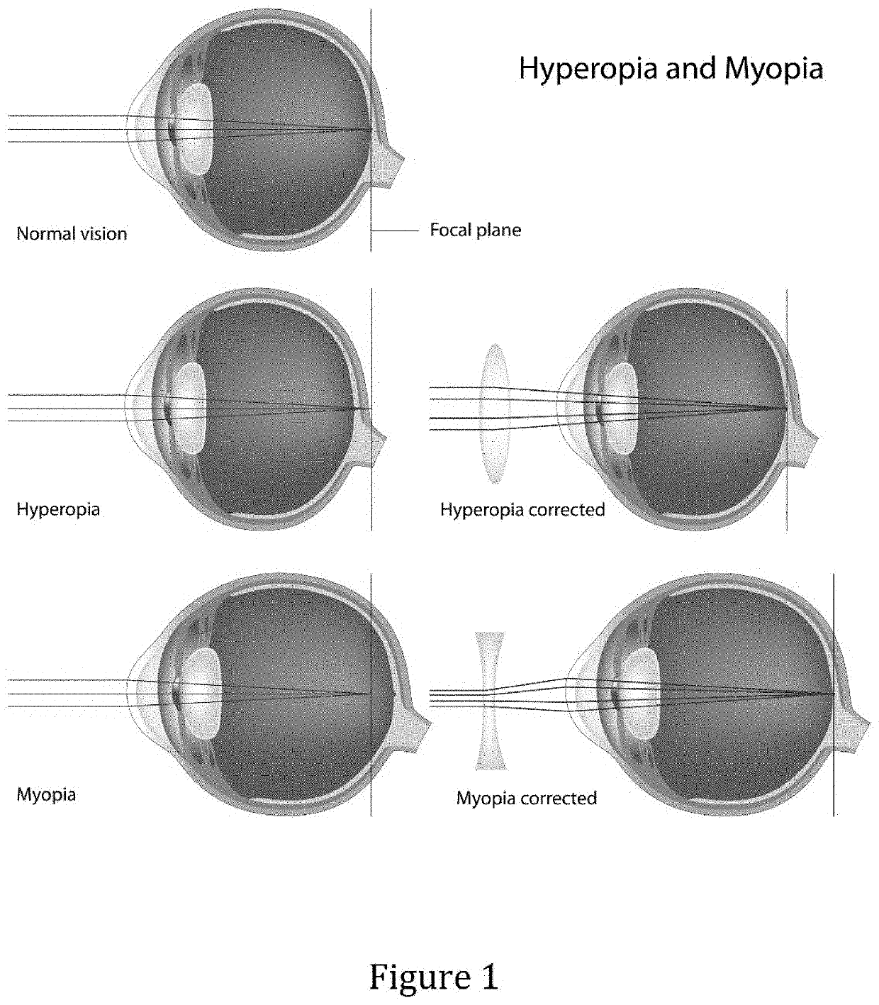
[0026]Some of the main defects being examined for are conditions such as myopia, hyperopia and astigmatism. These conditions are shown in FIG. 1.

[0027]Myopia is where the light that comes in does not directly focus on the retina but in front of it, causing the image that o...


PUM


Abstract

The current invention is a Photorefractive Flash Device and System. It is a device that can be clipped to any portable computing device to illuminate the pupil in a way, that allows a proper pupillary reflex. On the backside of the device is a photoreceptor, on the frontside—facing the persons eyes are LEDs, centered around an opening where the lens of the camera looks through. A smartphone-app triggers the flashlight of the camera. The photoreceptor of the device senses this flash and triggers the six LEDs to flash sequentially within 200 milliseconds. 200 milliseconds is the time, the pupil needs to react. By staying under this 200 milliseconds, it can achieve high-quality pictures of the pupillary reflection, before the pupil contracts.

Description

CROSS-REFERENCES TO RELATED APPLICATIONS[0001]NoneFIELD OF THE INVENTION[0002]This invention refers to the field of photorefractive flash device and method to measure and achieve high-quality pictures of the pupillary reflection.BACKGROUND OF THE INVENTION[0003]Ophthalmology and Optometry are health care professions concerned with the health of the eyes. Ophthalmologists, Optometrists are trained to prescribe and fit lenses to improve vision, and to diagnose and treat various eye diseases. Opticians are trained to fit lenses to improve vision.[0004]Corrective lenses are used to correct refractive errors of the eye by bending the light entering the eye in order to alleviate the effects of conditions such as myopia, hyperopia and astigmatism.[0005]Myopia, which is also known as nearsightedness, is where the light that comes in does not directly focus on the retina but in front of it, causing the image that one sees when looking at a distant object to be out of focus, but in focus when...

Claims


Application Information

Patent Timeline
Patent Type & Authority Patents(United States)
IPC IPC(8): G02B26/08A61B3/103A61B3/00A61B3/036A61B3/14
CPCA61B3/0008A61B3/036A61B3/14A61B3/1035A61B3/103
Inventor REIS, ALEXANDERGANAHL, WERNERBOHLER, LUKASSCHAEFFEL, FRANK
Owner REIS ALEXANDER
Why Eureka
Try Eureka