Analysis system and optical element replacement timing determination method

an analysis system and timing determination technology, applied in the direction of optical radiation measurement, instruments, spectrometry/spectrophotometry/monochromators, etc., can solve the problems of failure in which the analytical precision worsens, the light amount of the light detected by the light detector might not meet the predetermined amount, and the optical element is contaminated with dirt and deterioration, so as to achieve the effect of adequate assurance of the light amount of the light detected by the light detector

Active Publication Date: 2020-01-21
SHIMADZU CORP
View PDF9 Cites 0 Cited by
  • Summary
  • Abstract
  • Description
  • Claims
  • Application Information

AI Technical Summary

Benefits of technology

[0029]According to the aspect of the present invention, the replacement timing determination unit determines the replacement timing of the optical element based on the light amount of the light detected by the light detector while the light source is not deteriorating. Therefore, the replacement timing of the optical element is correctly determined. As a result, the light amount of the light detected by the light detector is adequately assured.

Problems solved by technology

With respect to the above conventional analytical device, even when the light source is replaced, the light amount of the light detected by the light detector might not meet the predetermined amount.
And while using the analytical device, such an optical element is contaminated with dirt and deteriorates due to ultraviolet light.
In such a way, with respect to the above conventional analytical device, even when the light source is replaced, the light amount of the light detected by the light detector might not meet the required amount resulting in the failure in which the analytical precision worsens.

Method used


Image

  • Analysis system and optical element replacement timing determination method
  • Analysis system and optical element replacement timing determination method
  • Analysis system and optical element replacement timing determination method

Examples


embodiment 2

5. Embodiment 2

[0116]Hereafter, the inventor sets forth the analysis system 10 according to the aspect of the Embodiment 2 of the present invention referring to FIG. 6. In addition, the same unit as illustrated according to the aspect of the Embodiment 1 is not set forth while providing the identical reference sign.

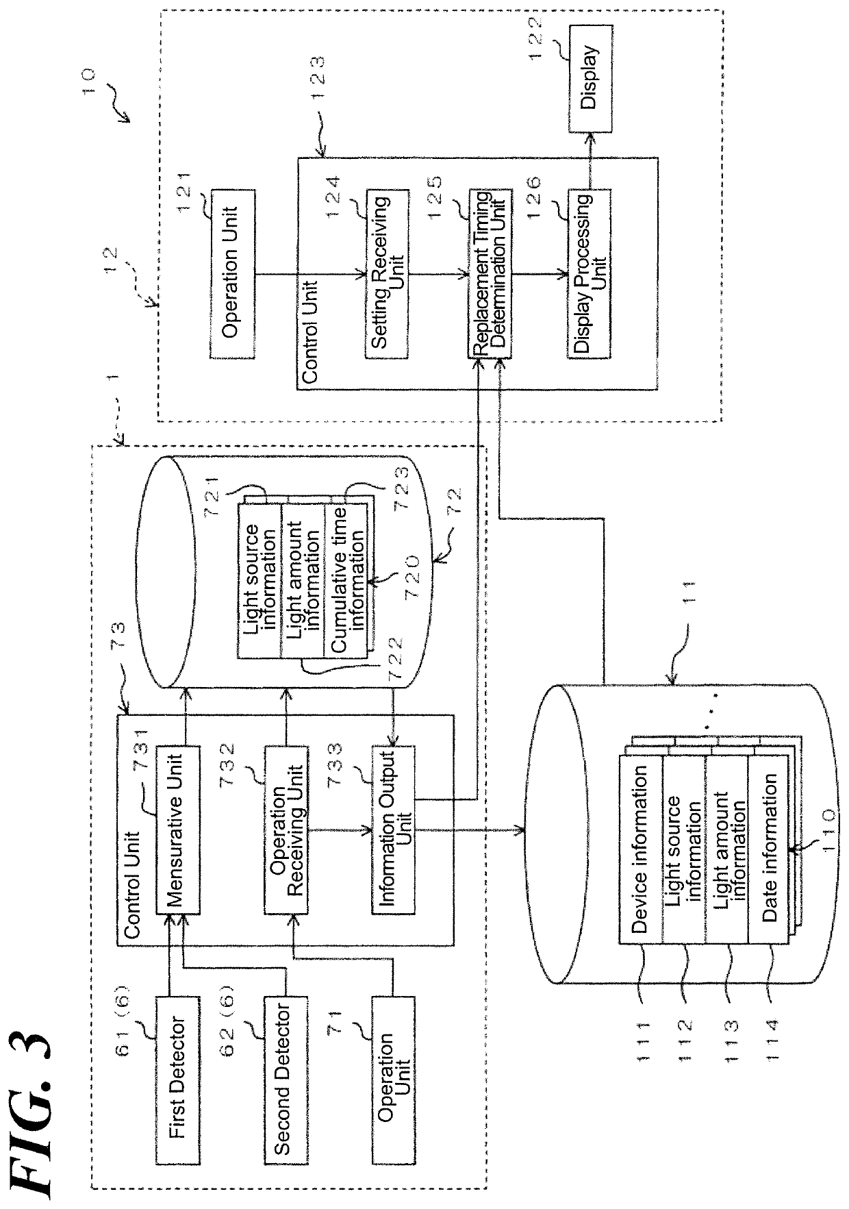
[0117]FIG. 6 is a block diagram illustrating an electrical configuration of the analysis system 10 according to the aspect of the Embodiment 2 of the present invention.

[0118]According to the aspect of the Embodiment 1, the replacement timing determination unit 125 of the control terminal 12 reads out the control information 110 in the memory device 11 and then, determines the replacement timing of the optical element based on the light amount information 113 of the read-out control information 110.

[0119]Whereas, according to the aspect of the Embodiment 2, the replacement timing determination unit 125 of the control terminal 12 determines the replacement timing of the opt...


PUM

PropertyMeasurementUnit
thresholdaaaaaaaaaa
timeaaaaaaaaaa
threshold valueaaaaaaaaaa

Abstract

An analysis system 10 includes a plurality of spectrophotometers 1, a memory storage 11, and a control terminal 12. The spectrophotometer 1 further includes a light source 2, a light detector, and an optical element that introduces light from the light source 2 to the light detector. The memory device 11 stores the information as the control information 110 relative to the light amount of the light detected by the light detector 6 right after replacement when replacing the light source of the spectrophotometer 1. A replacement timing determination unit 125 of the control terminal 12 reads out a control information 110 in the memory device 11 and determines the replacement timing of the optical element based on the value of the light amount information of the read-out control information 110.

Description

CROSS REFERENCE TO RELATED APPLICATIONS[0001]This application relates to, and claims priority from, Ser. No. JP2017-202489 filed on Oct. 19, 2017, the entire contents of which are incorporated herein by reference.FIGURE SELECTED FOR PUBLICATION[0002]FIG. 1BACKGROUND OF THE INVENTIONField of the Invention[0003]The present invention relates to an analysis system comprising a light source that radiates light and an optical element that reflects or transmits the light irradiated from the light source and a determination method of replacement timing of the optical element of the analysis system.Description of the Related Art[0004]Conventionally, an analytical device is widely used to carry out an analysis in which the light is radiated to the sample and the light from the sample is measured. In addition, a plurality of analysis devices is connected to a network and an analysis system uses such analysis devices that are controlled with a control terminal via the network.[0005](1) The anal...

Claims


Application Information

Patent Timeline
Patent Type & Authority Patents(United States)
IPC IPC(8): G01J3/42G01J3/10G01N21/15G01J3/28G01J3/02
CPCG01J3/2803G01N21/15G01J3/42G01J3/10G01J3/027G01N2021/157G01J2003/106G01N2201/127G01J3/02G01M11/02G01N21/01
Inventor ZUSHI, JUMPEI
Owner SHIMADZU CORP
Why Eureka
Try Eureka