Power-oriented bus encoding for data transmission

a technology of data transmission and power-oriented buses, which is applied in the field of power-oriented bus encoding for data transmission, can solve the problems of increasing the power consumption of data movement over the variety of interconnections in a system, increasing the power consumption, and increasing the bus toggle rate, so as to achieve the effect of increasing the power consumption and increasing the power consumption

Active Publication Date: 2020-01-21
ADVANCED MICRO DEVICES INC
View PDF24 Cites 2 Cited by
  • Summary
  • Abstract
  • Description
  • Claims
  • Application Information

AI Technical Summary

Problems solved by technology

The power consumption of data movement over the variety of interconnections in a system typically increases as the amount of traffic increases in the system.
However, when data is compressed, portions of the interconnects (e.g., a bus) are not used to transmit valid data.
While these unused portions may not be carrying desired data, they nevertheless may cause unnecessary toggling on the corresponding wires which in turn increases power consumption.
If the bus width increases to match the widths of other interfaces and provide a targeted bandwidth, then the bus toggle rate, and accordingly the power consumption, increases.

Method used


Image

  • Power-oriented bus encoding for data transmission
  • Power-oriented bus encoding for data transmission
  • Power-oriented bus encoding for data transmission

Examples


Embodiment Construction

[0019]In the following description, numerous specific details are set forth to provide a thorough understanding of the methods and mechanisms presented herein. However, one having ordinary skill in the art should recognize that the various embodiments may be practiced without these specific details. In some instances, well-known structures, components, signals, computer program instructions, and techniques have not been shown in detail to avoid obscuring the approaches described herein. It will be appreciated that for simplicity and clarity of illustration, elements shown in the figures have not necessarily been drawn to scale. For example, the dimensions of some of the elements may be exaggerated relative to other elements.

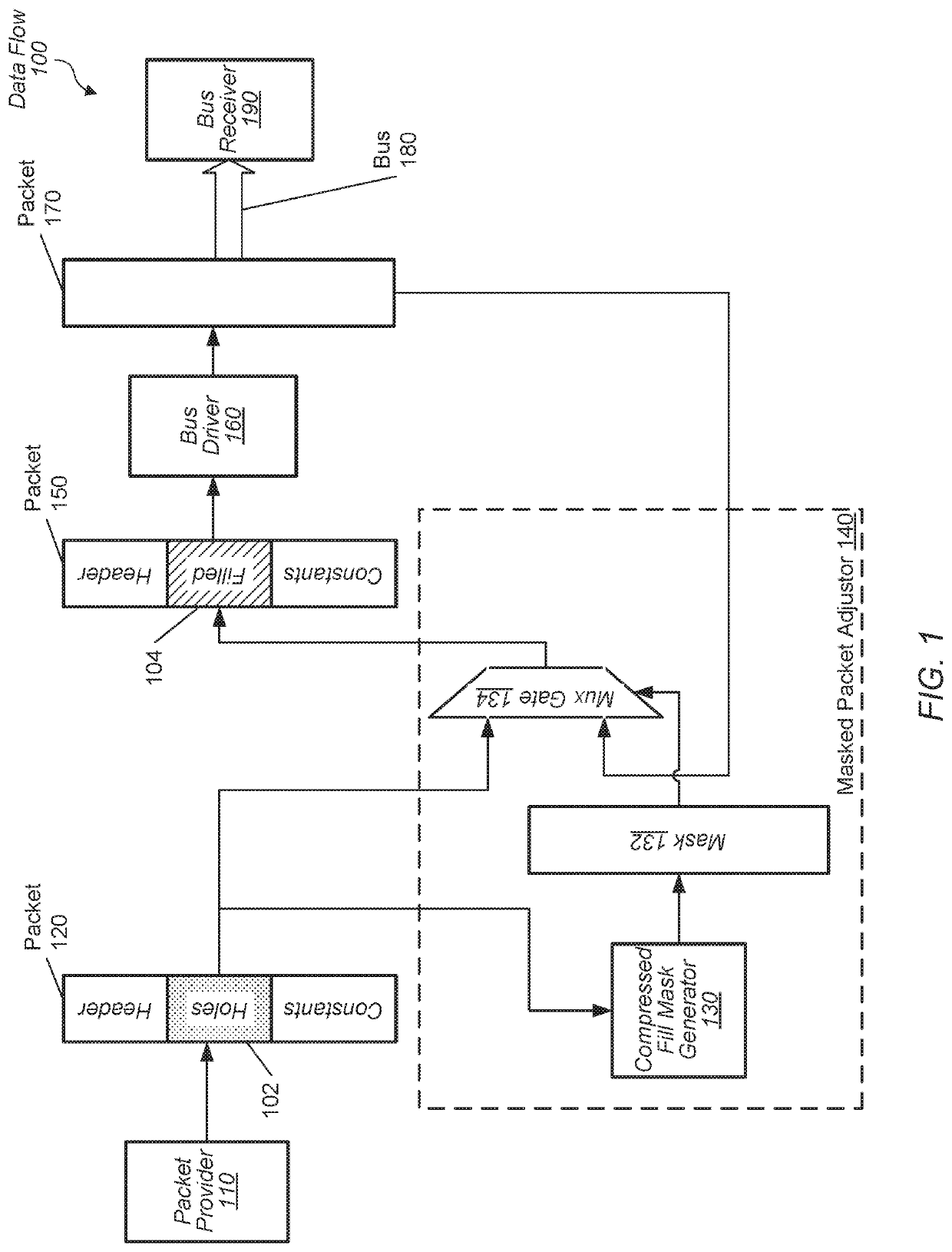
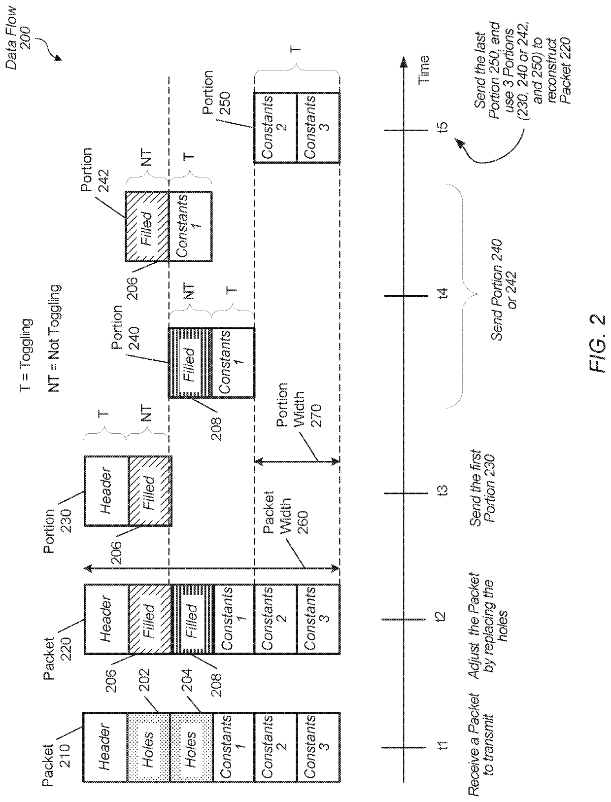
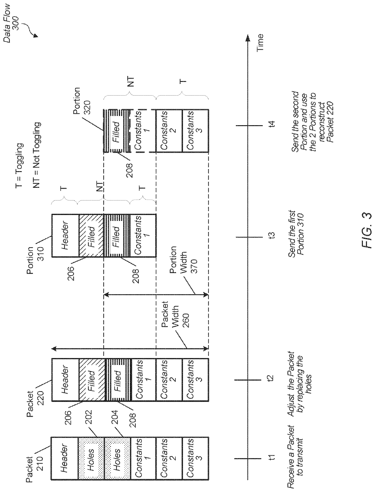
[0020]Various systems, apparatuses, methods, and computer-readable mediums for reducing the toggle rates on buses are disclosed. In various embodiments, a computing system includes a source which provides data for transmission on a bus or on a link. In one embodi...


PUM


Abstract

Systems, apparatuses, and methods for reducing the toggle rates on buses are disclosed. A computing system includes a source which provides packets for transmission on a bus. The packet is compressed by a compression engine. The compressed data format of the packet includes locations (bit positions) referred to as holes which do not include valid data. A bus configuration module identifies the locations of the holes and replaces the holes with information from a previous packet transmitted earlier on the bus. The bus configuration module also determines a new transmission bus width for the packet for lowering the bus toggle rate on the bus during transmission.

Description

[0001]This invention was made with Government support under (FastForward-2 Memory Technology (MT) Project with Lawrence Livermore National Laboratory) Prime Contract No. DE-AC52-07NA27344, Subcontract No. B609201 awarded by the United States Department of Energy. The United States Government has certain rights in this invention.BACKGROUNDDescription of the Related Art[0002]Semiconductor chips are often fabricated that include memory and one or more processors configured to process instructions. In some embodiments, the processors and the memory are on a same die. In other embodiments, the processing unit and the memory are on different dies within a same package such as a system-on-a-chip (SOC). In yet other embodiments, the processors and the memory are on different packages such as separate processing nodes. The instruction processing includes fetching instructions and data, decoding instructions, executing instructions, and storing results. Therefore, the one or more processors g...

Claims


Application Information

Patent Timeline
Patent Type & Authority Patents(United States)
IPC IPC(8): G06F13/16G06F13/40
CPCG06F13/1678G06F13/4072G06F1/3253G06F13/4204Y02D10/00
Inventor SADOWSKI, GREGNGUYEN, TRI MINH
Owner ADVANCED MICRO DEVICES INC
Why Eureka
Try Eureka