Check patentability & draft patents in minutes with Patsnap Eureka AI!

Angular error detecting device

a detection device and angular error technology, applied in the direction of transmission monitoring, receiver monitoring, electrical equipment, etc., can solve the problem of blocking the accurate calculation of angular error

Active Publication Date: 2020-01-21
NIHON DEMPA KOGYO CO LTD
View PDF14 Cites 0 Cited by
  • Summary
  • Abstract
  • Description
  • Claims
  • Application Information

AI Technical Summary

Benefits of technology

The invention is a system that can adjust the direction of an antenna to align with a communication satellite. The system uses a tracking system to automatically align the antenna with the satellite. This improves the quality of the communication signal and makes it easier to receive information from the satellite.

Problems solved by technology

On the other hand, in the tracking receiving system, a calculating machine that calculates the angular error is not necessarily able to be arranged at a position near the antenna.
However, when lengths of these signal paths are not strictly aligned, a phase difference between the sum signal and the difference signal is formed to become a factor that blocks an accurate calculation of the angular error.
However, Japanese Unexamined Patent Application Publication No. 56-500394 and Japanese Unexamined Patent Application Publication No. 2010-66069 do not disclose a technique that detects the phase difference caused by the respective signal paths in real time without performing the switching between the sum signal / the difference signal and the pilot signals to utilize it for the correction.

Method used


Image

  • Angular error detecting device
  • Angular error detecting device
  • Angular error detecting device

Examples


Embodiment Construction

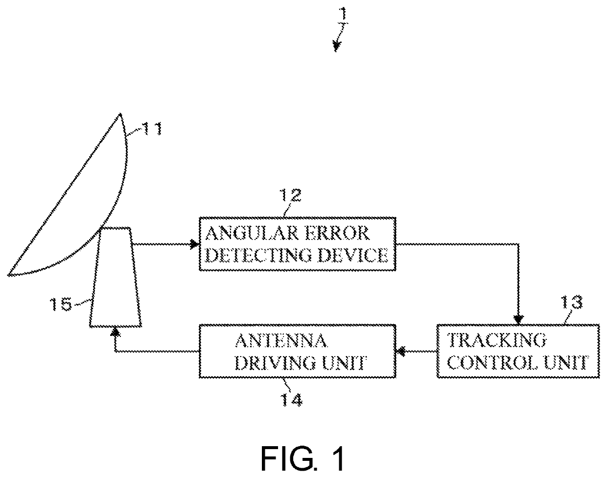
[0023]FIG. 1 illustrates an exemplary configuration of a tracking receiving system 1 that includes an angular error detecting device according to an embodiment of this disclosure.

[0024]This tracking receiving system 1 includes an antenna 11, an antenna driving mechanism 15, an angular error detecting device 12, a tracking control unit 13, and an antenna driving unit 14. The antenna 11 receives a communication signal (a frequency signal) output from a tracking target. The antenna driving mechanism 15 changes a direction of this antenna 11. The angular error detecting device 12 detects a deviation (an angular error) in a receiving direction of the communication signal with respect to a front direction of the antenna 11, based on a sum signal and a difference signal of the communication signal obtained from the antenna 11. The tracking control unit 13 obtains a driving direction and a driving amount of the antenna 11 based on the angular error detected at the angular error detecting de...


PUM


Abstract

An angular error detecting device detects an angular error in a receiving direction of a frequency signal from a tracking target with respect to a front direction of an antenna based on a phase difference of a first reception signal received at a first receiving unit of the antenna and a second reception signal received at a second receiving unit having a receiving position in the antenna different from a receiving position of the first receiving unit. The angular error detecting device includes a reception signal output unit, a pilot signal supply unit, a pilot phase difference detection unit, a correction unit, and an angular error detection unit. The angular error detection unit detects the angular error based on the one side corrected at the correction unit and the other side that is not corrected of the sum signal and the difference signal.

Description

CROSS-REFERENCE TO RELATED APPLICATIONS[0001]This application claims the priority benefits of Japanese Patent Application No. 2018-140009, filed on Jul. 26, 2018. The entirety of the above-mentioned patent application is hereby incorporated by reference herein and made a part of this specification.TECHNICAL FIELD[0002]This disclosure relates to a technique that detects an angular error of an antenna with respect to a tracking target.DESCRIPTION OF THE RELATED ART[0003]A receiving system that receives a communication signal as a frequency signal output from a tracking target such as a communication satellite includes one (a tracking receiving system) configured to change a direction of an antenna such that a receiving direction of the communication signal is aligned with a front direction of the antenna, based on a result of detection of a deviation (an angular error) of the receiving direction of the communication signal with respect to the front direction of the antenna.[0004]As a ...

Claims


Application Information

Patent Timeline
Patent Type & Authority Patents(United States)
IPC IPC(8): H04B17/00H04B17/21H04B17/27
CPCH04B17/21H04B17/27H04B17/12
Inventor KOBAYASHI, KAORUONISHI, NAOKI
Owner NIHON DEMPA KOGYO CO LTD
Features
  • R&D
  • Intellectual Property
  • Life Sciences
  • Materials
  • Tech Scout
  • Unparalleled Data Quality
  • Higher Quality Content
  • 60% Fewer Hallucinations
Learn More