[0006]Hence, it is an aspect of the invention to provide an alternative lighting device, which preferably further at least partly obviates one or more of above-described drawbacks, and which may have a relatively good efficiency and a high intensity, and which may also be scalable.
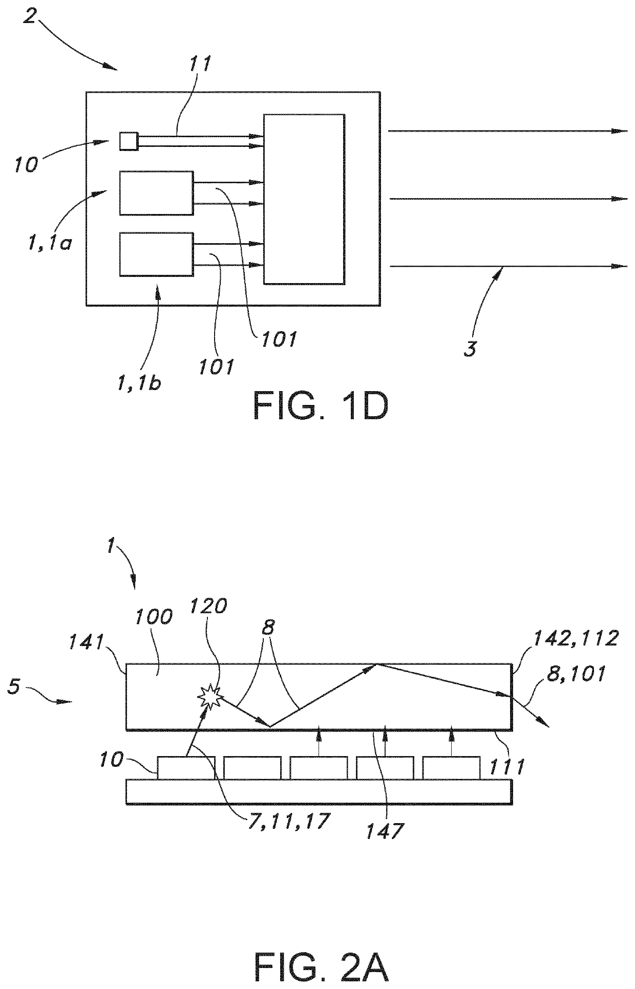
[0013]Hence, the invention uses instead of a single large light concentrator a plurality of (smaller) light concentrators as light sources to pump a single light concentrator. This principle may be used in a configuration with a concentrator-concentrator functional coupling, in a concentrator-concentrator-concentration functional coupling, and optionally even further cascades may be possible. The first concentrators especially provides Stokes-shifted light which is used to pump the second concentrator, and optionally the second concentrator(s) may again be used to pump a third concentrator. In this way reabsorption losses may be minimized and scalability is introduced. Further, the final light intensity can be much higher than with a single large light concentrator, as e.g. highly optimized concentrators can be used to pump the downstream concentrator instead of light sources.
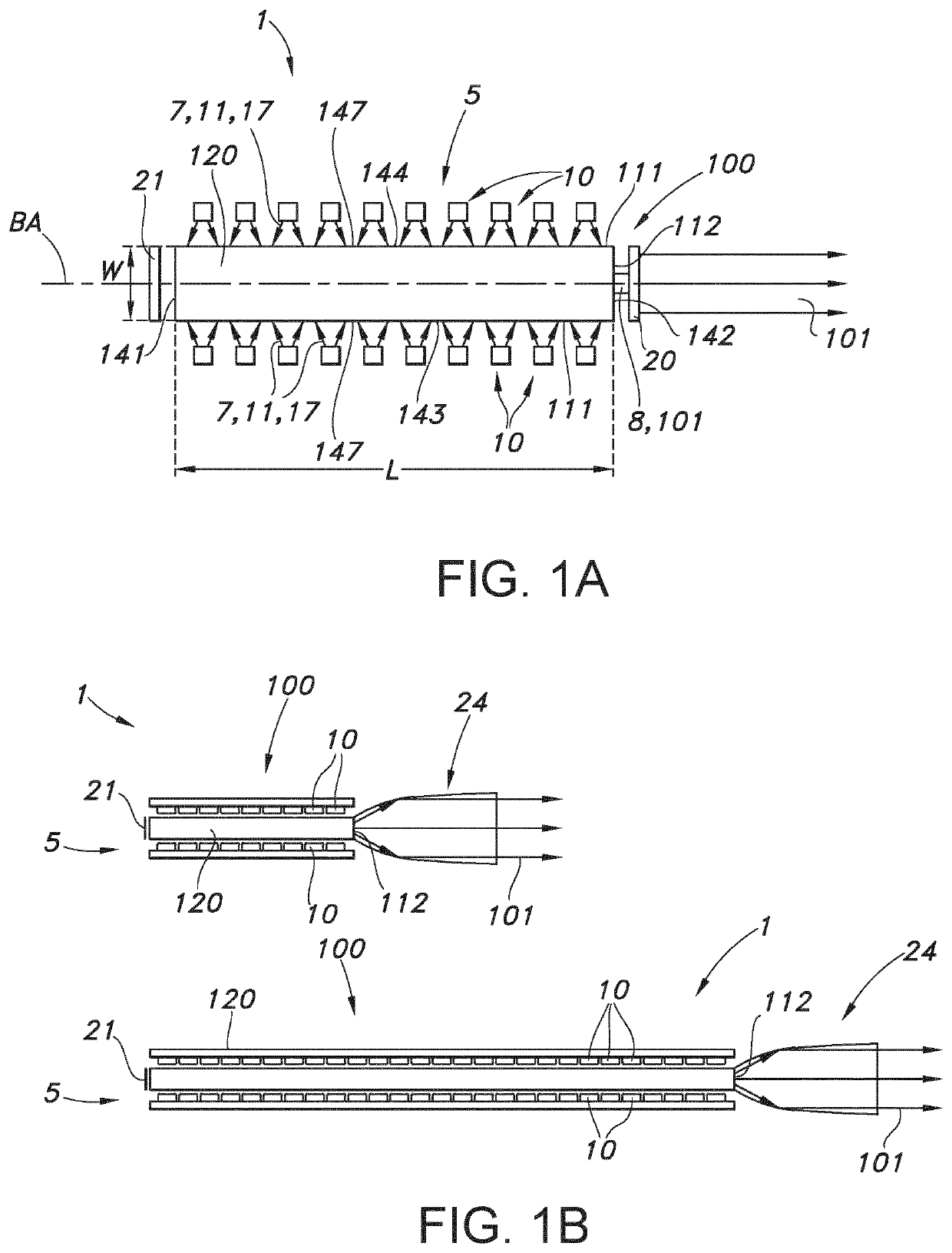
[0025]The light transmissive body as set forth below in embodiments according to the invention may also be folded, bended and / or shaped in the length direction such that the light transmissive body is not a straight, linear bar or rod, but may comprise, for example, a rounded corner in the form of a 90 or 180 degrees bend, a U-shape, a circular or elliptical shape, a loop or a 3-dimensional spiral shape having multiple loops. This provides for a compact light transmissive body of which the total length, along which generally the light is guided, is relatively large, leading to a relatively high lumen output, but can at the same time be arranged into a relatively small space. For example luminescent parts of the light transmissive body may be rigid while transparent parts of the light transmissive body are flexible to provide for the shaping of the light transmissive body along its length direction. The light sources may be placed anywhere along the length of the folded, bended and / or shaped light transmissive body.
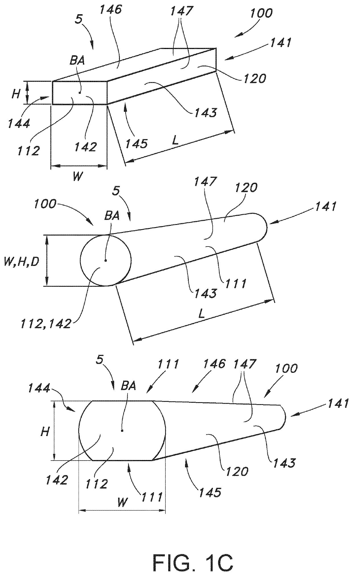
[0046]However, when desired the luminescent concentrators that are used as pumps may also be configured under a non-perpendicular angle. Especially, each luminescent concentrator comprises a body axis (BA). Hence, in embodiments the plurality of first luminescent concentrators includes two or more subsets of first luminescent concentrators configured with an angle of the body axis (BA) of the first luminescent concentrator and the body axis (BA) of the second luminescent concentrator unequal to 90°, such as in the range of at least 5° to smaller than 90°, such as 15-45°. Angles unequal to 90° may especially be useful for low surface reflection.
[0047]In yet further embodiments, the elongated light transmissive body of one or more luminescent concentrators comprise an elongated ceramic body. For instance, luminescent ceramic garnets doped with Ce3+ (trivalent cerium) can be used to convert blue light into light with a longer wavelength, e.g. within the green to red wavelength region, such as in the range of about 500-750 nm. To obtain sufficient absorption and light output in desired directions, it is advantageous to use transparent rods (especially substantially shaped as beams). Such rod can be used as light concentrator, concentrating over their length light source light from light sources such as LEDs (light emitting diodes), converting this light source light into converter light and providing at an exit surface a substantial amount of converter light. Lighting devices based on light concentrators may e.g. be of interest for projector applications. For projectors, red and green luminescent concentrators are of interest. Green luminescent rods, based on garnets, can be relatively efficient. Such concentrators are especially based on YAG:Ce (i.e. Y3Al5O12:Ce3+) or LuAG (Lu3Al5O12:Ce3+). ‘Red’ garnets can be made by doping a YAG-garnet with Gd (“YGdAG”). Doping of Gd, however, results in a lower thermal stability (thermal quenching). Red-shifting can also be obtained using a high Ce concentration, with a much smaller penalty for thermal stability.
[0058]Quantum dots are small crystals of semiconducting material generally having a width or diameter of only a few nanometers. When excited by incident light, a quantum dot emits light of a color determined by the size and material of the crystal. Light of a particular color can therefore be produced by adapting the size of the dots. Most known quantum dots with emission in the visible range are based on cadmium selenide (CdSe) with a shell such as cadmium sulfide (CdS) and zinc sulfide (ZnS). Cadmium free quantum dots such as indium phosphode (InP), and copper indium sulfide (CuInS2) and / or silver indium sulfide (AgInS2) can also be used. Quantum dots show very narrow emission band and thus they show saturated colors. Furthermore the emission color can easily be tuned by adapting the size of the quantum dots. Any type of quantum dot known in the art may be used in the present invention. However, it may be preferred for reasons of environmental safety and concern to use cadmium-free quantum dots or at least quantum dots having a very low cadmium content.



