
Actuated outlet door for aircraft high-temperature exhaust

a technology of high-temperature exhaust and actuator, which is applied in the direction of de-icing equipment, power plant cooling arrangements, transportation and packaging, etc., can solve the problems of leaving room for improvement, and achieve the effect of reducing the thermal footprint of hot exhaust on the aircraft skin and reducing aircraft drag

Active Publication Date: 2020-02-04
BOMBARDIER CORP
View PDF25 Cites 0 Cited by
  • Summary
  • Abstract
  • Description
  • Claims
  • Application Information

AI Technical Summary

Benefits of technology

The present invention is about a way to cool down hot gas from a jet engine by using a device that creates a pressure difference between two regions. This helps to keep the hot exhaust gases away from the aircraft's skin, reducing the temperature and the impact on the aircraft's performance. The invention also includes an articulated door that only opens when needed, which can help reduce the amount of drag on the aircraft. Overall, this cooling system helps to improve the efficiency and reliability of jet engines.

Problems solved by technology

The known apparatuses, methods, and systems, however leave room for improvement.

Method used


Image

  • Actuated outlet door for aircraft high-temperature exhaust
  • Actuated outlet door for aircraft high-temperature exhaust
  • Actuated outlet door for aircraft high-temperature exhaust

Examples


second embodiment

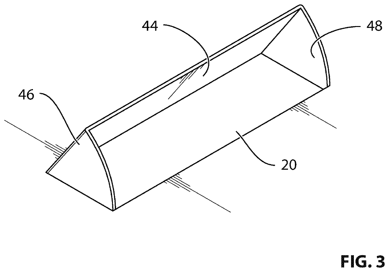
[0079]FIG. 3 is a simple, perspective illustration of an actuated outlet door 44 according to the present invention. In this embodiment, the actuated outlet door 44 includes a first side panel 46 and a second side panel 48. The side panels 46, 48 are contemplated, in selected constructions, to improve the aerodynamic properties of the actuated outlet door 44 by discouraging freestream air 32 from flowing around the side edges of the actuated outlet door 44.

third embodiment

[0080]FIG. 4 is a perspective, graphical illustration of an actuated outlet door 50 of the present invention, shown in an opened condition.

[0081]The actuated outlet door 50 includes a number of vortex generators 52 on its inner surface 54. The vortex generators 52 are intended to be illustrative of how the inner surface 54 of the actuated outlet door 50 might be altered to change the mixing between the heated air 26 and the freestream air 32.

[0082]In FIG. 4, the vortex generators 52 are positioned closer to the leading edge 56 of the actuated outlet door 50 than the trailing edge 58. While the vortex generators 52 are illustrated near to the leading edge 56 of the actuated outlet door 50, the vortex generators 52 are contemplated to be positioned at any location and / or position on the inner surface 54 of the actuated outlet door 50, between the leading edge 56 and the trailing edge 58. It is noted that the leading edge 56 is positioned toward the front of the aircraft 12 and the tra...

fourth embodiment

[0083]FIG. 5 is a cross-sectional, graphical illustration of the present invention. In this embodiment, one or more exhaust vanes 60 are positioned within the exhaust duct 30. The exhaust vanes 60 help to change flow direction of the heated air 26 as it passes through the exhaust duct 30 and exits through the outlet opening 20. In this embodiment, the actuated outlet door 10 is configured in the same (or similar) manner as the actuated outlet door 10 shown in FIG. 1. As should be apparent, however, any embodiment for the actuated outlet door 10 may be employed without departing from the scope of the present invention.


PUM


Abstract

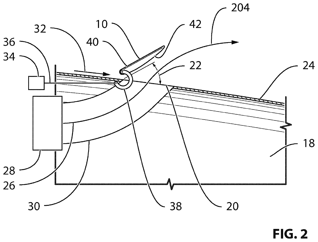
An outlet door is provided for covering an outlet defining an outlet area in a skin (24) of an aircraft component to exhaust a flow of heated air to an outside of the aircraft. The outlet door includes a body defining a door area and extending between a leading edge and a trailing edge and a linkage (38) connecting the body to the aircraft, permitting the body to transition between at least one of an open position and a closed position. In the closed position, the body at least partially occupies the outlet area. In the open position, the body forms an angle with the skin of the aircraft. The leading edge of the body and the skin of the aircraft define a separation (202) therebetween when the body is in the open position. The separation defines and air flow for mixing cold air with the flow of heated air.

Description

CROSS-REFERENCE TO RELATED APPLICATION(S)[0001]This application is a national phase application under 35 U.S.C. 371 of International Patent Application No. PCT / IB2015 / 055735 filed on Jul. 29, 2015, which claims priority from U.S. Provisional Patent Application Ser. No. 62 / 039,648 filed on Aug. 20, 2014, the entire content of which is incorporated herein by reference.FIELD OF THE INVENTION[0002]The present invention concerns an actuated door for an aircraft high-temperature exhaust outlet. More specifically, the present invention concerns the construction of an exhaust door that facilitates exhaustion of hot gases from, for example a jet engine pre-cooler, while minimizing the impact of the exhaustion of the hot gases on the aerodynamic and / or thermal properties of the aircraft.DESCRIPTION OF THE RELATED ART[0003]In the prior art, there are examples of operation of aircraft pre-coolers, which might generate heated gases that must be exhausted therefrom.[0004]One example may be found ...

Claims


Application Information

Patent Timeline
Patent Type & Authority Patents(United States)
IPC IPC(8): B64D33/04B64D33/08B64D15/04
CPCB64D33/04B64D33/08B64D15/04
Inventor IAROCCI, NICKSADRI, REZAPOIRIER, VINCENTDUSSAULT, KATHLEENBOILEAU, EDMOND
Owner BOMBARDIER CORP
Learn More