

Anti-icing device
A technology of anti-icing device and anti-icing system, which is applied in the direction of de-icing device, transportation and packaging, aircraft parts, etc., can solve problems such as adverse effects on aerodynamic performance, and achieve the effects of improving separation control ability, simple structure and reducing aircraft resistance.
- Summary
- Abstract
- Description
- Claims
- Application Information
AI Technical Summary
Problems solved by technology
Method used
Image

Examples
Embodiment 1
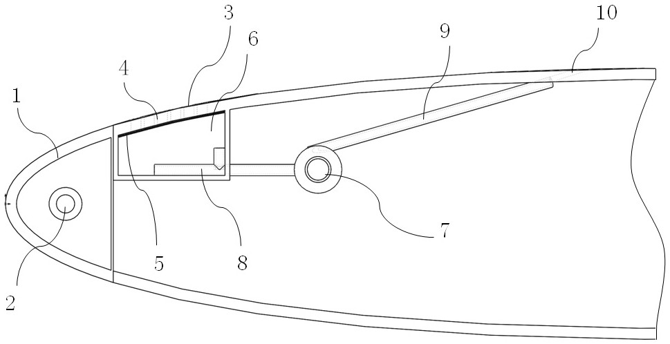
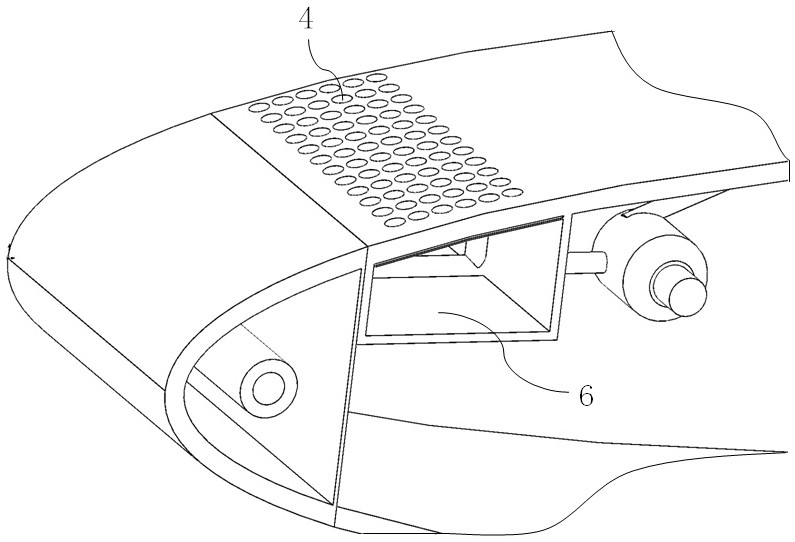
[0029] An anti-icing device such as figure 1 As shown, including the anti-icing system 2 arranged at the aerodynamic leading edge 1, micropores 4 are partially or completely arranged on the skin of the wing downstream of the anti-icing system 2 to form a microporous skin 3; in the microporous skin 3 Below is provided with at least one airtight cabin 6; also comprises suction device 7, and the suction pipe 8 of suction device 7 stretches in the airtight cabin 6, and the exhaust pipe 9 of suction device 7 connects the exhaust port on the wing 10. The suction device 7 can be an air pump.
[0030] Wherein, the anti-icing system 2 is a conventional electric anti-icing, hot air anti-icing, mechanical anti-icing system, and the anti-icing system here is a conventional anti-icing system, which will not be repeated here. The microporous skin 3 is arranged on the wing downstream of the anti-icing system, mainly to collect the overflow water formed by the anti-icing system 2 for anti-i...
Embodiment 2
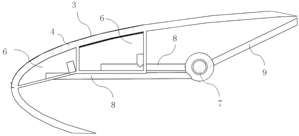
[0036] The difference between this embodiment and Embodiment 1 is that the anti-icing system 2 is no longer provided in this embodiment, but a microporous skin is provided on the windward surface of the wing.
[0037] Specifically, such as image 3 As shown, the microporous skin 3 is extended to the aerodynamic leading edge, and different airtight cabins and air extraction ducts can be set separately according to needs, such as image 3Among them, in the present embodiment, an airtight cabin 6 is provided downstream of the aerodynamic front edge 1, equipped with an air suction duct 8, and an airtight cabin 6 is provided at the aerodynamic front edge 1, equipped with an air suction duct 8, and two The suction pipes 8 all have multiple branches, so as to improve the efficiency of suction. Certainly, the quantity of airtight cabin, suction duct can not be used as the restriction to the present invention in the present implementation, in fact, in the accompanying drawing of prese...
PUM
 Abstract
Description
Claims
Application Information