
Center fuel tank assembly with partitioned center fuel tank for an aircraft and methods of sequencing fuel for the same

a fuel tank and center fuel technology, applied in liquid fuel feeders, machines/engines, transportation and packaging, etc., can solve the problems of increasing structural weight and complexity of known systems and methods, and achieve the effects of reducing aircraft drag, minimizing any added structural weight, and minimizing complexity

Active Publication Date: 2020-10-20
THE BOEING CO
View PDF3 Cites 0 Cited by
  • Summary
  • Abstract
  • Description
  • Claims
  • Application Information

AI Technical Summary

Benefits of technology

[0008]Example implementations of this disclosure provide for such an aircraft center fuel tank assembly and method for shifting the center of gravity (CG) aftward to reduce aircraft drag, while also minimizing any added structural weight and minimizing any increased complexity. As discussed in the below detailed description, versions of the aircraft center fuel tank assembly and method may provide significant advantages over known aircraft fuel tank assemblies and methods.
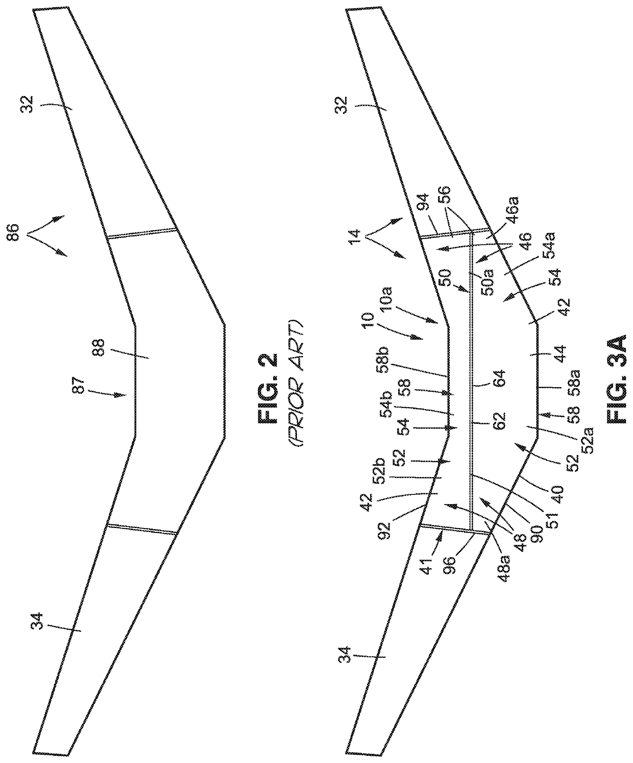
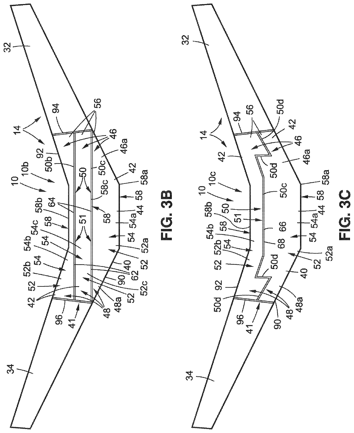
[0011]The center fuel tank assembly further comprises a fuel flow control assembly coupled to each of the two or more separate sub-tanks. Each fuel flow control assembly operates independently. A sequential fuel burn of the fuel in the two or more separate sub-tanks is made in a fore-to-aft sequence while the aircraft is in flight, to assist in shifting aftward a center of gravity (CG) of the aircraft, to reduce aircraft drag.
[0015]The center fuel tank assembly further comprises one or more access openings formed through each of the two or more separate sub-tanks. The center fuel tank assembly further comprises a fuel quantity indicator coupled to each of the two or more separate sub-tanks and further coupled to a fuel quantity indication system (FQIS) for the aircraft (12a) that calculates a usable fuel quantity in each of the two or more separate sub-tanks. The center fuel tank assembly further comprises one or more nitrogen generation system (NGS) distribution elements coupled to each of the two or more separate sub-tanks and configured to distribute nitrogen-enriched air (NEA) for a nitrogen generation system (NGS) for the aircraft (12a). A sequential fuel burn of the fuel in the two or more separate sub-tanks is made in a fore-to-aft sequence while the aircraft is in flight. This assists in shifting aftward a center of gravity (CG) of the aircraft, to reduce aircraft drag.
[0021]The method further comprises the step of evenly using fuel loaded in the first main fuel tank and the second main fuel tank, after using any fuel loaded in the partitioned center fuel tank. The fore-to-aft sequence of sequencing use of fuel in the aircraft in flight assists in shifting aftward a center of gravity (CG) of the aircraft, to reduce aircraft drag.

Problems solved by technology

However, such known systems and methods may have increased structural weight due to added fuel tanks and fuel system components required for such aft body and horizontal tail systems and methods.
Moreover, such known systems and methods may have increased complexity due to additional redundant design features required to safeguard against a possibility of fuel being left in an aft body tank or a horizontal tail tank.

Method used


Image

  • Center fuel tank assembly with partitioned center fuel tank for an aircraft and methods of sequencing fuel for the same
  • Center fuel tank assembly with partitioned center fuel tank for an aircraft and methods of sequencing fuel for the same
  • Center fuel tank assembly with partitioned center fuel tank for an aircraft and methods of sequencing fuel for the same

Examples


Embodiment Construction

[0038]Disclosed versions or embodiments will now be described more fully hereinafter with reference to the accompanying drawings, in which some, but not all of the disclosed versions or embodiments are shown. Indeed, several different versions or embodiments may be provided and should not be construed as limited to the versions or embodiments set forth herein. Rather, these versions or embodiments are provided so that this disclosure will be thorough and fully convey the scope of the disclosure to those skilled in the art.

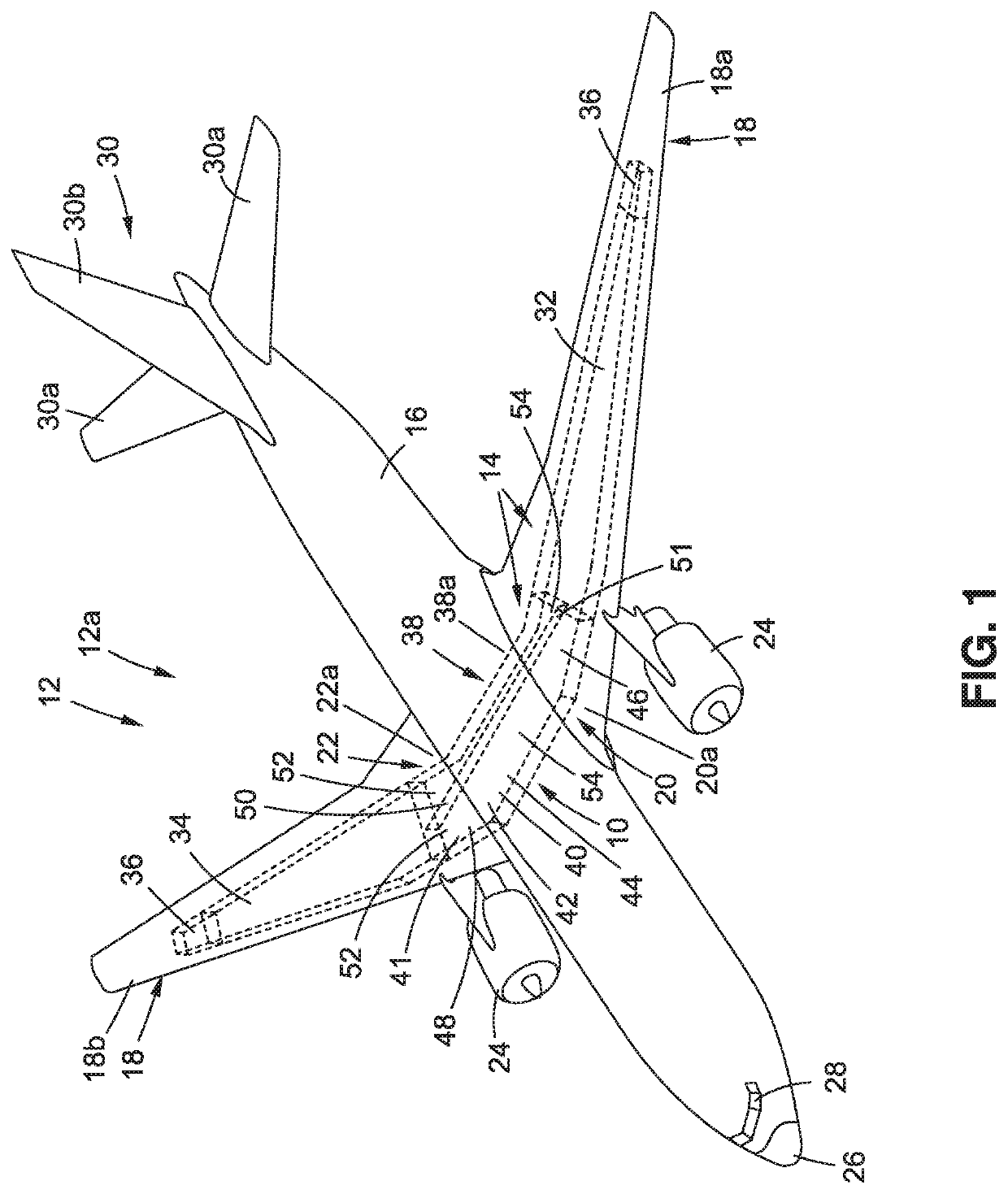
[0039]Now referring to the Figures, and in particular, with reference to FIG. 1, in one version of the disclosure there is provided a center fuel tank assembly 10 for a vehicle 12, such as in the form of an aircraft 12a. FIG. 1 is an illustration of a front perspective view of the vehicle 12, such as in the form of aircraft 12a, having a fuel tank arrangement 14 that incorporates a version of the center fuel tank assembly 10 of the disclosure. As shown in FIG. 1, t...


PUM


Abstract

There is provided a center fuel tank assembly for an aircraft. The assembly includes a center fuel tank disposed in a central part of the aircraft. The assembly further includes one or more fuel barrier members partitioning the center fuel tank into two or more separate volume sections comprising two or more separate sub-tanks arranged in a fore-to-aft alignment to form a partitioned center fuel tank. The assembly further includes a fuel flow control assembly coupled to each of the two or more separate sub-tanks, each fuel flow control assembly operating independently. A sequential fuel burn of fuel in the two or more separate sub-tanks is made in a fore-to-aft sequence while the aircraft is in flight, to assist in shifting aftward a center of gravity (CG) of the aircraft, to reduce aircraft drag.

Description

BACKGROUND[0001]1) Field of the Disclosure[0002]The disclosure relates generally to fuel tank assemblies and methods for aircraft, and more particularly, to center wing fuel tank assemblies and methods for commercial and military jet aircraft.[0003]2) Description of Related Art[0004]The fuel tank assemblies of large commercial and military jet aircraft may include a main fuel tank located in each of the wings of the aircraft and a center fuel tank located between the main fuel tanks. Prior to a planned flight of such aircraft, a quantity of fuel needed for the planned flight is determined, and such fuel is typically first loaded evenly into the main fuel tanks, and after the main fuel tanks are fully loaded, if additional fuel is needed, such additional fuel is typically loaded into the center fuel tank. Large commercial and military jet aircraft may use the center fuel tank to store a significant volume of fuel which may weigh up to 30% of a maximum takeoff weight of the aircraft. ...

Claims


Application Information

Patent Timeline
Patent Type & Authority Patents(United States)
IPC IPC(8): B64C17/10F02M37/00B64D37/04B64C3/34B65D90/44B60K15/077
CPCB64D37/04B64C3/34F02M37/0094B64C17/10B60K15/077B65D90/44
Inventor BARON, LENNARD T.SCHULZE, TODD W.RYDELL, THEODORE N.PURCELL, TIMOTHY W.MULVANEY, PATRICK J.
Owner THE BOEING CO
Learn More