anti-icing device

A technology of anti-icing device and anti-icing system, which is applied in the direction of de-icing device, transportation and packaging, aircraft parts, etc. Effect

Active Publication Date: 2021-08-10
LOW SPEED AERODYNAMIC INST OF CHINESE AERODYNAMIC RES & DEV CENT
View PDF14 Cites 0 Cited by
  • Summary
  • Abstract
  • Description
  • Claims
  • Application Information

AI Technical Summary

Problems solved by technology

However, the existing scheme of using compressed air source or synthetic jet to set air blowing downstream of the thermal protection area of ​​the aerodynamic surface, the selection of the air blowing position is limited by the range of the thermal protection area (need to be set immediately downstream of the thermal protection), and it is possible to set the pneumatic blowing jet adversely affect aerodynamic performance

Method used


Image

  • anti-icing device
  • anti-icing device
  • anti-icing device

Examples


Embodiment 1

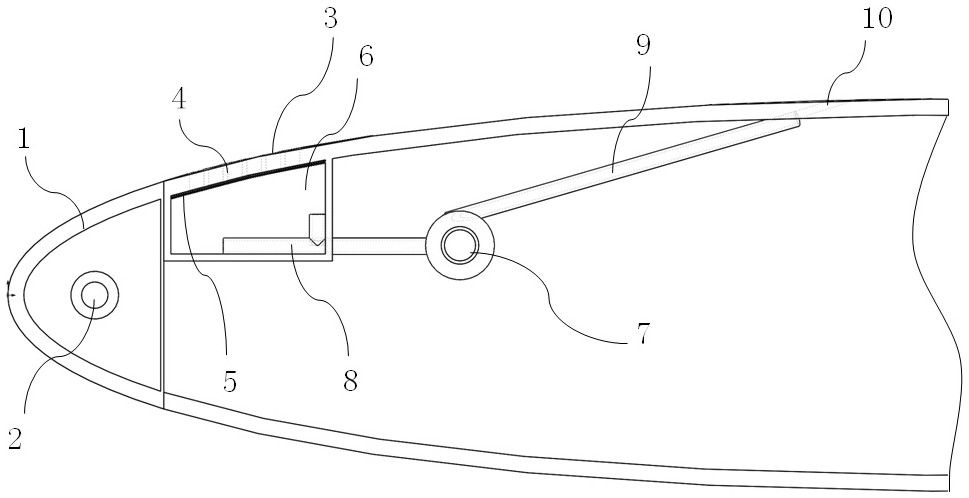
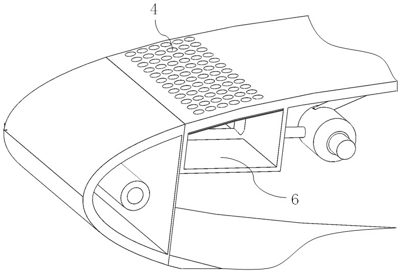
[0029] An anti-icing device such as figure 1 As shown, including the anti-icing system 2 arranged at the aerodynamic leading edge 1, micropores 4 are partially or completely arranged on the skin of the wing downstream of the anti-icing system 2 to form a microporous skin 3; in the microporous skin 3 Below is provided with at least one airtight cabin 6; also comprises suction device 7, and the suction pipe 8 of suction device 7 stretches in the airtight cabin 6, and the exhaust pipe 9 of suction device 7 connects the exhaust port on the wing 10. The suction device 7 can be an air pump.

[0030] Wherein, the anti-icing system 2 is a conventional electric anti-icing, hot air anti-icing, mechanical anti-icing system, and the anti-icing system here is a conventional anti-icing system, which will not be repeated here. The microporous skin 3 is arranged on the wing downstream of the anti-icing system, mainly to collect the overflow water formed by the anti-icing system 2 for anti-i...

Embodiment 2

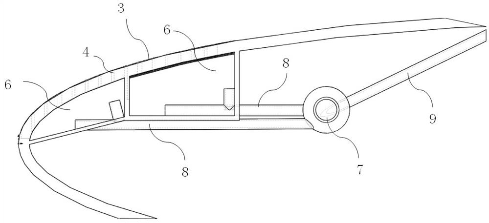
[0036] The difference between this embodiment and Embodiment 1 is that the anti-icing system 2 is no longer provided in this embodiment, but a microporous skin is provided on the windward surface of the wing.

[0037] Specifically, such as image 3 As shown, the microporous skin 3 is extended to the aerodynamic leading edge, and different airtight cabins and air extraction ducts can be set separately according to needs, such as image 3Among them, in the present embodiment, an airtight cabin 6 is provided downstream of the aerodynamic front edge 1, equipped with an air suction duct 8, and an airtight cabin 6 is provided at the aerodynamic front edge 1, equipped with an air suction duct 8, and two The suction pipes 8 all have multiple branches, so as to improve the efficiency of suction. Certainly, the quantity of airtight cabin, suction duct can not be used as the restriction to the present invention in the present implementation, in fact, in the accompanying drawing of prese...


PUM


Abstract

The invention is applicable to the technical field of aircraft anti-icing, and provides an anti-icing device. An anti-icing system is arranged on the aerodynamic leading edge, and micropores are partially or completely arranged on the skin of the wing downstream of the anti-icing system to form a microporous skin. ; at least one airtight cabin is set under the microporous skin; it also includes a suction device, the suction pipe of the suction device extends into the airtight chamber, and the exhaust pipe of the suction device Connect the exhaust ports on the wings. The micropores in the microporous skin can effectively "inhale" the turbulent boundary layer, and can also maintain most of the laminar boundary layer of the wing, which can reduce aircraft resistance and improve the separation control ability of the aerodynamic surface, thereby improving the fuel economy of the aircraft. The present invention adopts a system to simultaneously meet the requirements of artificial laminar flow control and overflow water control; the deicing device of the present invention does not require additional air supply, has a simple structure, can be implemented in modules, and is convenient to be applied to light aircraft and unmanned aerial vehicles.

Description

technical field [0001] The invention relates to the technical field of aircraft anti-icing, in particular to an anti-icing device. Background technique [0002] Icing is one of the main causes of aircraft flight accidents. Icing on the leading edge of the wings and tail of the aircraft will lead to increased airfoil resistance, decreased lift, reduced critical angle of attack, and deterioration of maneuverability and stability, resulting in Serious flight accidents have received widespread attention and research. According to the different forms of energy used in anti-icing, it can be divided into mechanical anti-icing systems, electric pulse anti-icing systems, liquid anti-icing systems, hot air anti-icing systems and electric thermal anti-icing systems. The program is currently widely used. [0003] Anti-icing systems focus on aerodynamic surfaces directly impacted by droplets, such as the leading edge of an airfoil, but in some cases, such as high water content in cloud...

Claims


Application Information

Patent Timeline
Patent Type & Authority Patents(China)
IPC IPC(8): B64D15/04B64D15/12B64D15/16
CPCB64D15/04B64D15/12B64D15/16
Inventor 胡站伟丁亮易贤赵献礼
Owner LOW SPEED AERODYNAMIC INST OF CHINESE AERODYNAMIC RES & DEV CENT
Why Eureka
Try Eureka