Suicide-preventing fence

a technology of suicide prevention and fence, applied in the direction of bridges, bridge structural details, instruments, etc., can solve the problems of tarnishing the national image, and achieve the effects of preventing suicide, generating electric energy by the wind, and preventing suicid

Active Publication Date: 2020-02-04
ALUMIZONE
View PDF14 Cites 0 Cited by
  • Summary
  • Abstract
  • Description
  • Claims
  • Application Information

AI Technical Summary

Benefits of technology

[0013]Accordingly, the rotating bodies are provided on the fence, and hence it is possible to prevent suicide by making it difficult for a person attempting to pass over the fence to grasp the fence. In addition, the rotating ropes are wound around the rotating bodies so that the rotating ropes are not pulled out even when pulled, and thereby it is possible to prevent suicide. In addition, it is possible to warn when suicide attempt is made by detecting a load of the person attempting to pass over the fence and generating an alarm signal. Further, it is possible to generate electric energy by the wind.

Problems solved by technology

Currently, threatening to commit suicide at a bridge is not merely considered as a sort of happening, but is becoming a social problem, and it is in urgent need to take measures to prevent suicide attempt and threat.
The suicide attempt and threat at a bridge is not only a personal matter but also a waste of manpower due to input of personnel from private and public organizations to prevent the suicide attempt and threat, and causes various discomforts of citizens, such as traffic congestion, and a social problem such as a national image being tarnished.
However, in the aforementioned related art, a cylindrical guide rail is configured to be rotatable, but there are drawbacks in that a person attempting suicide can grip the guide rail with hands and can even more easily pass over the bridge rail using the guide rail rotating.

Method used


Image

  • Suicide-preventing fence
  • Suicide-preventing fence
  • Suicide-preventing fence

Examples


Embodiment Construction

[0021]Hereinafter, exemplary embodiments of the present invention will now be described fully with reference to the accompanying drawings. Terms described below are selected by considering functions according to exemplary embodiments, and may vary depending on a user or operator's intention, or precedents and so on. Therefore, in the following embodiments, when terms are specifically defined, the meanings of terms should be interpreted based on definitions, and otherwise, should be interpreted based on general meanings recognized by those skilled in the art.

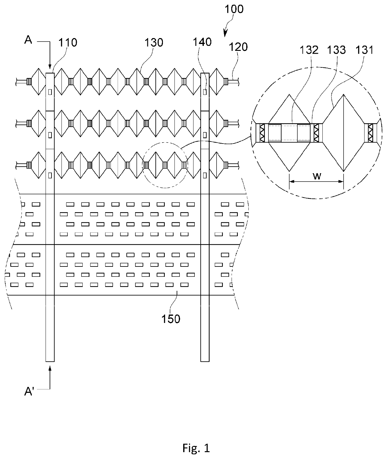
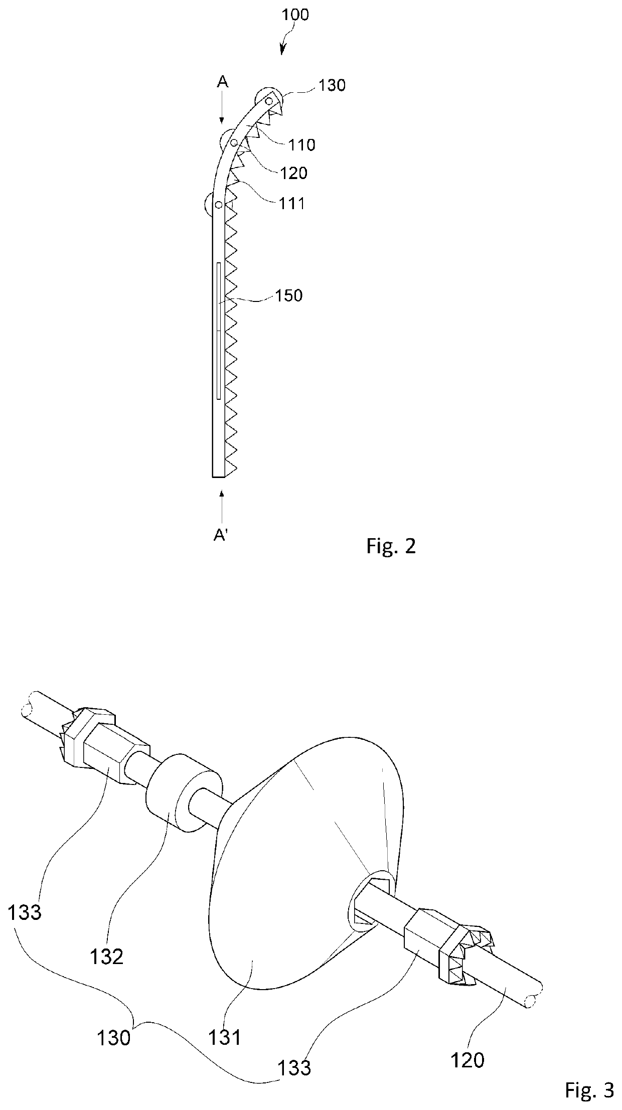
[0022]FIG. 1 is a configuration diagram of a suicide-preventing fence according to one embodiment of the present invention, and FIG. 2 is a cross-sectional view of the suicide-preventing fence taken along line A-A′ of FIG. 1.

[0023]Referring to FIGS. 1 and 2, the suicide-preventing fence 100 according to one embodiment of the present invention includes pole parts 110, linking parts 120, and rotating parts 130.

[0024]A plurality of ...


PUM


Abstract

A suicide preventing fence including: a plurality of pole parts provided standing upright from the ground surface at predetermined intervals, and a plurality of linking parts which are formed in the shape of pipes and horizontally link the spaces between the pole parts. The fence further includes rotating bodies which are formed with an internally hollow abacus bead shape and are provided on the outer circumferential surfaces of the linking parts, and bearings which are provided on the outer circumferential surfaces of the linking parts, positioned in the centers on the insides of the rotating bodies. The fence further includes rotating bolts which are provided on the outer circumferential surfaces of the linking parts and are inserted in through passing regions on both side surfaces of the rotating bodies so as to rotate together with the rotating bodies.

Description

CROSS-REFERENCE TO RELATED PATENT APPLICATION[0001]This application claims the benefit of Korean Patent Application No. 10-2014-0175711, filed on Dec. 9, 2014, in the Korean Intellectual Property Office, the disclosure of which is incorporated herein in its entirety by reference.TECHNICAL FIELD[0002]The present invention relates to a suicide-preventing fence, and more specifically, to a technology for preventing a person who attempts to commit suicide from passing over a fence by installing a suicide-preventing fence on a bridge rail.BACKGROUND ART[0003]Currently, threatening to commit suicide at a bridge is not merely considered as a sort of happening, but is becoming a social problem, and it is in urgent need to take measures to prevent suicide attempt and threat. The suicide attempt and threat at a bridge is not only a personal matter but also a waste of manpower due to input of personnel from private and public organizations to prevent the suicide attempt and threat, and causes ...

Claims


Application Information

Patent Timeline
Patent Type & Authority Patents(United States)
IPC IPC(8): E04H17/00G08B21/02E01D19/10G08B21/18
CPCG08B21/18E04H17/003G08B21/02E01D19/10E01D19/103E04H17/1413G08B13/122E04H17/004
Inventor HER, SONG WOO
Owner ALUMIZONE
Why Eureka
Try Eureka