
Electronic detonator storage device suitable for automatic filling

A technology of electronic detonators and detonator chambers, which is applied in the storage of ammunition, weapon accessories, fuzes, etc., and can solve the problems of failing to meet the requirements of a safe distance, short distance between detonators and explosives, and lack of physical isolation between detonators and explosives. To achieve the safety of the detonation system and reduce the effect of harmful effects

Pending Publication Date: 2021-11-02
六盘水华安爆破工程有限公司
View PDF0 Cites 0 Cited by
  • Summary
  • Abstract
  • Description
  • Claims
  • Application Information

AI Technical Summary

Problems solved by technology

[0004] During the construction in the pile well, due to the influence of the size of the pile well, the distance between the detonator and the explosive is very close, which is far from the requirement of the safe distance
As far as the current construction example is concerned, during the construction in the pile well, the detonator and the explosive are not physically separated, so there is a great potential safety hazard

Method used


Image

  • Electronic detonator storage device suitable for automatic filling
  • Electronic detonator storage device suitable for automatic filling
  • Electronic detonator storage device suitable for automatic filling

Examples


Embodiment Construction

[0025] The specific embodiments of the present invention will be further described below in conjunction with the accompanying drawings. It should be noted here that the descriptions of these embodiments are used to help understand the present invention, but are not intended to limit the present invention. In addition, the technical features involved in the various embodiments of the present invention described below may be combined with each other as long as they do not constitute a conflict with each other.

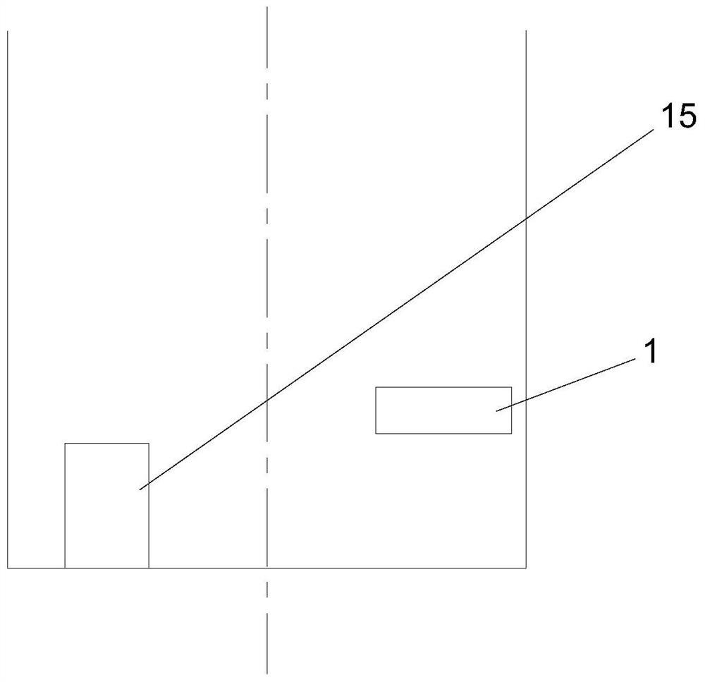
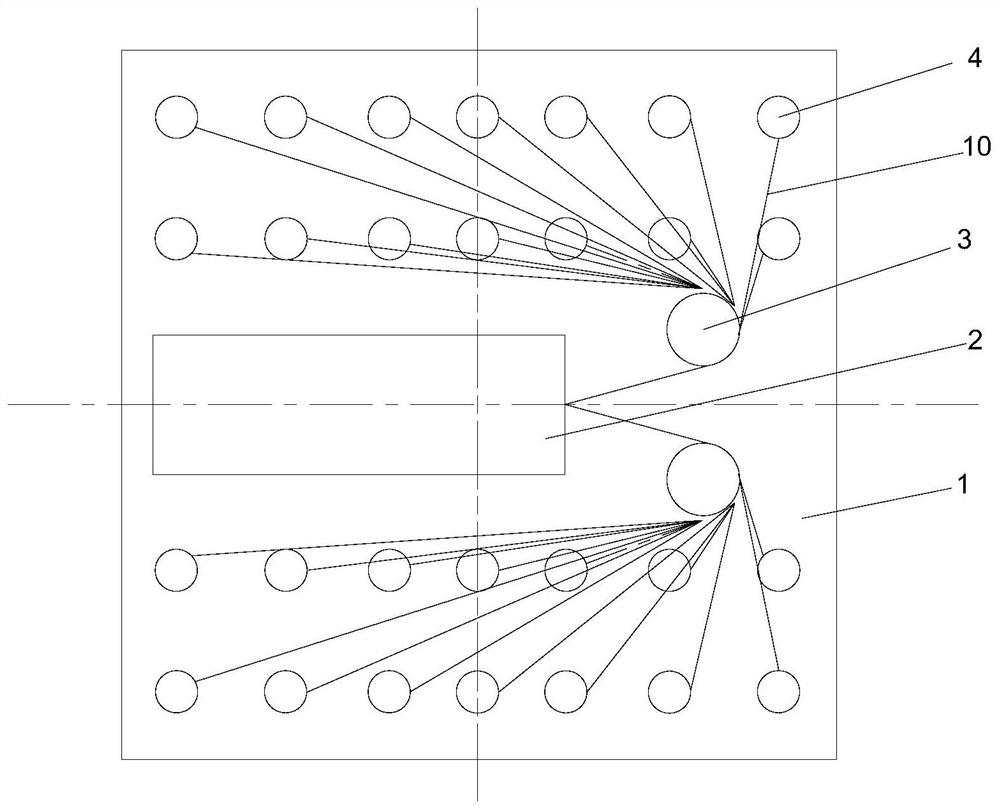
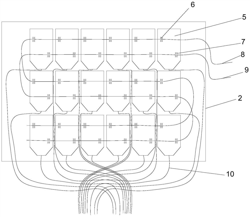
[0026] Such as Figure 1-5 As shown, an electronic detonator storage device suitable for automatic loading includes a detonator chamber 1 with the empty side facing upwards and installed at an angle of 90° to the explosive chamber 15. The detonator chamber 1 is internally provided with a detonator terminal clip A cluster box 2, one end of the detonator wiring clip cluster box 2 is provided with two winding posts 3, and two rows of detonator installation holes 4 are resp...


PUM


Abstract

The invention discloses an electronic detonator storage device suitable for automatic filling. The electronic detonator storage device comprises a detonator cabin with an upward free surface and an included angle of 90 degrees with an explosive cabin; a detonator jointing clamp bundling box is arranged in the detonator cabin; two wrapping posts are arranged at one end of the detonator jointing clamp bundling box; two rows of detonator mounting holes are respectively formed in two sides of the detonator jointing clamp bundling box at intervals; a plurality of rows of detonator jointing clamps are arranged in the detonator jointing clamp bundling box; the upper end of each row of detonator jointing clamp is provided with a first metal contact; the lower end of each row of detonator jointing clamp is provided with a second metal contact; the first metal contacts are connected in series through a first detonator bus; and the second metal contacts are connected in series through a second detonator bus. According to the electronic detonator storage device and the using method, detonators and explosives can be stored in an isolated mode; explosive sympathetic detonation caused by detonator mistaken detonation due to collision, extrusion and other factors is prevented; automation of explosive and detonator filling in a pile well is achieved; and the explosives and the detonators can be conveniently taken out at fixed positions through machines.

Description

technical field [0001] The invention relates to the technical field of electronic detonator storage, in particular to an electronic detonator storage device suitable for automatic filling. Background technique [0002] According to relevant safety regulations, detonators and explosives cannot be stored together. When the two are stored at the job site, they need to be stored separately, and the detonator should be stored in the detonator box, and a safe distance of more than 25 meters should be kept from the explosive to prevent the explosive from being detonated when the detonator is accidentally activated. [0003] When the detonator is activated, the charge in the detonator explodes, and the high-speed flying shrapnel formed by the detonator shell and the shock wave of the explosion are the detonation source of the explosive. If the shrapnel, heat source, shock wave, etc. when the detonator is excited are separated from the explosive by a certain distance, the detonator ...

Claims


Application Information

Patent Timeline
Patent Type & Authority Applications(China)
IPC IPC(8): F42B39/30F42C19/12
CPCF42B39/30F42C19/12
Inventor 瞿波余讯
Owner 六盘水华安爆破工程有限公司
Learn More