Apparatus and method for measuring 3D form or deformation of an object surface using a grid pattern and reference plane
a technology of object surface and reference plane, applied in the field of three-dimensional form measuring apparatus, can solve the problem that the measurement cannot be carried out for a moving image with little image data, and achieve the effect of poor space resolution
- Summary
- Abstract
- Description
- Claims
- Application Information
AI Technical Summary
Benefits of technology
Problems solved by technology
Method used
Image
Examples
first embodiment
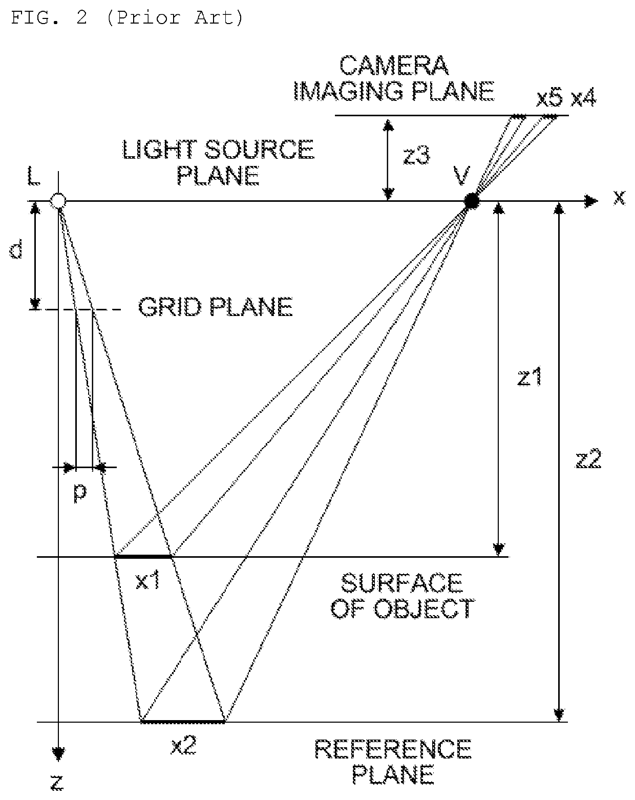
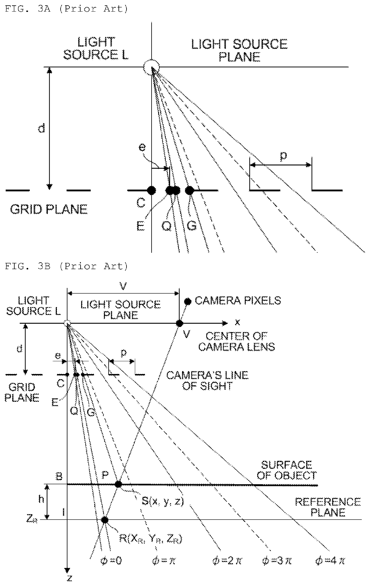
[0052]First, the measurement principle of the present invention is described.
[0053]The present invention provides a method for analyzing the phase from the brightness data of M pixels so that information on the height or the like can be gained from the phase by utilizing the fact that the pitch of the grid image always consists of a constant number of pixels, that is M pixels, when a one-dimensional grid is projected in accordance with a grid projection method.
[0054]FIGS. 2, 3A and 3B are schematic diagrams showing the grid projection mechanism of a form measuring apparatus and an object to be measured.
[0055]First, the optical system of a moire topography is further described in reference to FIG. 2.
[0056]L is the location of a light source, and V is the center of a camera lens. A grid is located at a distance d from the location L of the light source, where the width of one period is p.
[0057]In this optical system, the center V of the camera lens and the light source L of the projec...
second embodiment
[0145]The second embodiment relates to a form measurement method using a total space error table. Though the relationship between the phase and the height is found through calculation in the first embodiment, it is possible to find the phase of each pixel by using the technique for converting the total space into a table. Here, the technique for converting the total space into a table is a publicly-known technology as disclosed in Japanese Unexamined Patent Publication 2011-2378 (Wakayama University).
[0146]In accordance with the technique for converting the total space into a table, the relationship between the phase and the height (additionally, x, y and z coordinates) is found for each pixel in advance in order to gain a table. The height information can be gained simply by checking the table in the case where the phase is found. As a result, the calculation through triangulation becomes unnecessary, which makes the measurement very fast and an error originating from the optical s...
third embodiment
[0149]As described above, according to the present invention, the image data in a rectangular region (including a square, typically 3×3 pixels) is used for phase analysis. In the third embodiment of the present invention, two types of grids having different pitches in the x direction are used for the same region so as to analyze the respective phases, from the results of which phase unwrapping is carried out, and thus, a phase analysis method having a wide dynamic range can be implemented.
[0150]Two or more types of waves having different frequencies in the x direction are put into pixels in a rectangular region (including a square) so that the respective waves are separated and sampled from the brightness data of the image in this region using Fourier transform or the like, and then the phases of these waves are found (in reality, Fourier transform may not be used, and instead values may be substituted into Formula 7 for finding the phase that corresponds to the frequency 1 in order...
PUM
 Abstract
Description
Claims
Application Information
 - R&D
- Intellectual Property
- Life Sciences
- Materials
- Tech Scout
- Unparalleled Data Quality
- Higher Quality Content
- 60% Fewer Hallucinations
Browse by: Latest US Patents, China's latest patents, Technical Efficacy Thesaurus, Application Domain, Technology Topic, Popular Technical Reports.
© 2025 PatSnap. All rights reserved.Legal|Privacy policy|Modern Slavery Act Transparency Statement|Sitemap|About US| Contact US: help@patsnap.com


