
Exercise assembly for performing different rowing routines

a technology of exercise assembly and rowing routine, which is applied in the direction of gymnastic exercise, cardiovascular exercise devices, sport apparatus, etc., can solve the problems of increasing metabolism, unable to enable users to perform true rowing action, and relatively limited versatility of users, so as to achieve significant versatility

Active Publication Date: 2020-02-11
COREYAK LLC
View PDF75 Cites 6 Cited by
  • Summary
  • Abstract
  • Description
  • Claims
  • Application Information

AI Technical Summary

Benefits of technology

The exercise assembly described in this patent offers a unique and versatile way to work out by simulating the motion of kayaking or rows. The assembly allows users to perform different "rowing motions" or routines, making it easier for them to exercise and achieve their fitness goals. The assembly is suitable for people of all ages and genders. Overall, this invention offers a more effective and engaging way to train and work out.

Problems solved by technology

Further, weight training may increase muscle mass which in turn may result in an elevation in metabolism, a weight loss and in certain more specialized situations helps one in the performance of certain sports activities.
However, many known or conventional rowing machines provide user with relatively limited versatility in that many do not enable a user to perform a true rowing action corresponding to that if the user was in an actual rowboat, canoe or other preferred watercraft.
Further, many known conventional machines of this type are not capable of meaningful or selective adjustment which allow a user to change between different rowing routines, while concurrently making adjustments to accommodate the strength, size, age, etc. of different users.

Method used


Image

  • Exercise assembly for performing different rowing routines
  • Exercise assembly for performing different rowing routines
  • Exercise assembly for performing different rowing routines

Examples


Embodiment Construction

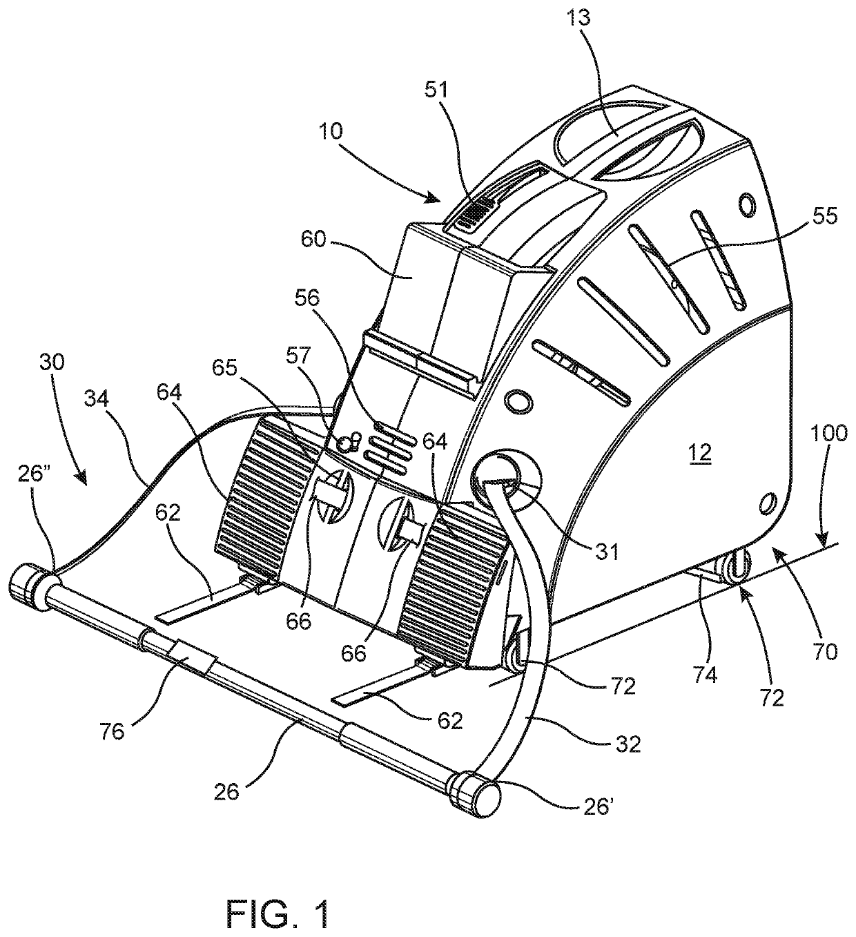
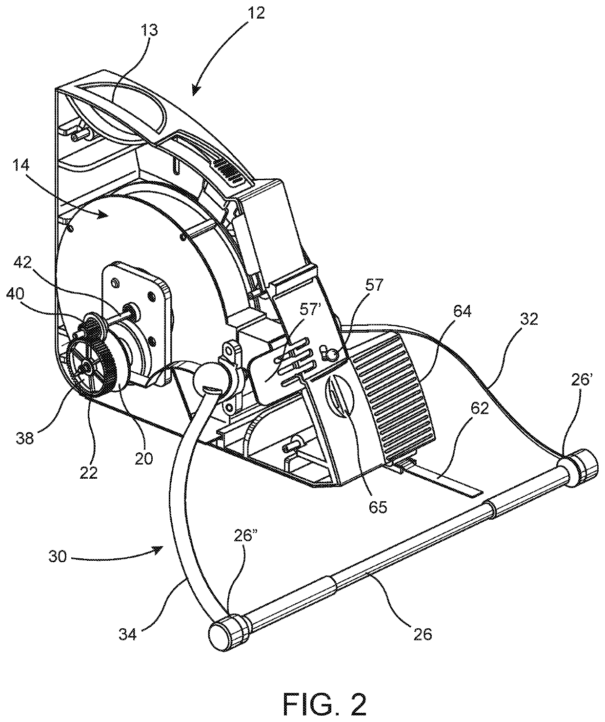
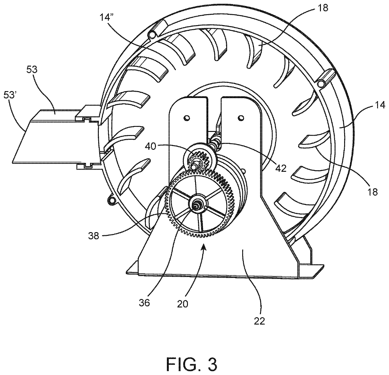
[0034]As represented in the accompanying Figures, the present invention is directed to an exercise assembly generally indicated as 10 including a housing 12 disposed in enclosing relation to a chamber generally indicated as 14. The chamber 14 as explained in greater detail with reference to FIGS. 3 and 4 may be more accurately and definitively described as an air chamber through which air flows and in which air is at least partially or temporarily retained. In addition, the exercise assembly 10 of the present invention includes a resistance device, generally indicated as 16, which is preferably in the form of fan or fan-like structure having a plurality of blades 18. The blades 18 are preferably, but not necessarily, disposed about an interior periphery of the resistance device / fan structure 16.

[0035]The resistance device 16 is rotationally driven within the interior 14′ of the air chamber 14 through activation of a drive assembly generally indicated as 20. The drive assembly 20 is ...


PUM


Abstract

An exercise assembly structured to perform different rowing routines characterized different rowing motions. A resistance device is movable within a chamber and is cooperatively structured therewith to resist such movement. A drive assembly includes two drive sections each independently connected in driving relation to said resistance device. A connector structure includes two connector members each attached to a handle and connected in driving relation to a different one of said drive sections. The handle is selectively movable through the plurality of different rowing motions, at least one of which results in the two drive sections concurrently driving the resistance member and being concurrently driven by the two connector members. At least one other rowing motion of the handle is defined by each drive section alternately driving the resistance member and being alternately driven by interconnected ones of said connector members.

Description

CLAIM OF PRIORITY[0001]The present Non-Provisional patent application claims priority pursuant to 35 U.S.C. Section 119(e) to a filed Provisional patent application, namely, that having Ser. No. 62 / 352,202 filed on Jun. 20, 2016, as well as to another filed Provisional application, namely, that having Ser. No. 62 / 419,618 filed on Nov. 9, 2016, the contents of which are both incorporated herein by reference in their entireties.BACKGROUND OF THE INVENTIONField of the Invention[0002]The present invention relates to novel land-based exercise devices that replicate the motion of kayaking and rowing. More particularly, the invention is related to an exercise device that replicates both the motion and resistance of kayaking and rowing and translates motion of the device's paddle handle into immediate corresponding motion of kayaking or rowing movement displayed in video games, videos, virtual reality videos and / or fitness tracking software.Description of the Related Art[0003]Physical fitne...

Claims


Application Information

Patent Timeline
IPC IPC(8): A63B21/008A63B71/06A63B21/00A63B22/00A63B24/00
CPCA63B71/0619A63B21/4035A63B22/0076A63B21/008A63B21/154A63B24/0003A63B2220/803A63B21/00069A63B21/0088A63B21/153A63B21/157A63B22/0005A63B22/001A63B22/20A63B71/0622A63B2022/0035A63B2022/0041A63B2022/0079A63B2024/0065A63B2024/0096A63B2069/068A63B2071/0638A63B2071/0647A63B2220/40A63B2225/50
Inventor MACHOVINA, BRIANMCHALE-MACHOVINA, EILEEN
Owner COREYAK LLC
Learn More