Trimmer blade modifier

Active Publication Date: 2020-02-11
TORRES CHUKA A
View PDF5 Cites 0 Cited by
  • Summary
  • Abstract
  • Description
  • Claims
  • Application Information

AI Technical Summary

Benefits of technology

[0015]Another object of the present invention is to provide a method for modifying a trimmer blade to add a face at a distal end of a facet of the trimmer blade to provide a sharper tip at a distal end of

Problems solved by technology

One problem with such trimmers is that there is generally a limit to the shortness with which hair can be cut, because the tip of the movable trimmer blade is somewhat blunt where a facet at a dista

Method used


Image

  • Trimmer blade modifier
  • Trimmer blade modifier
  • Trimmer blade modifier

Examples


Example

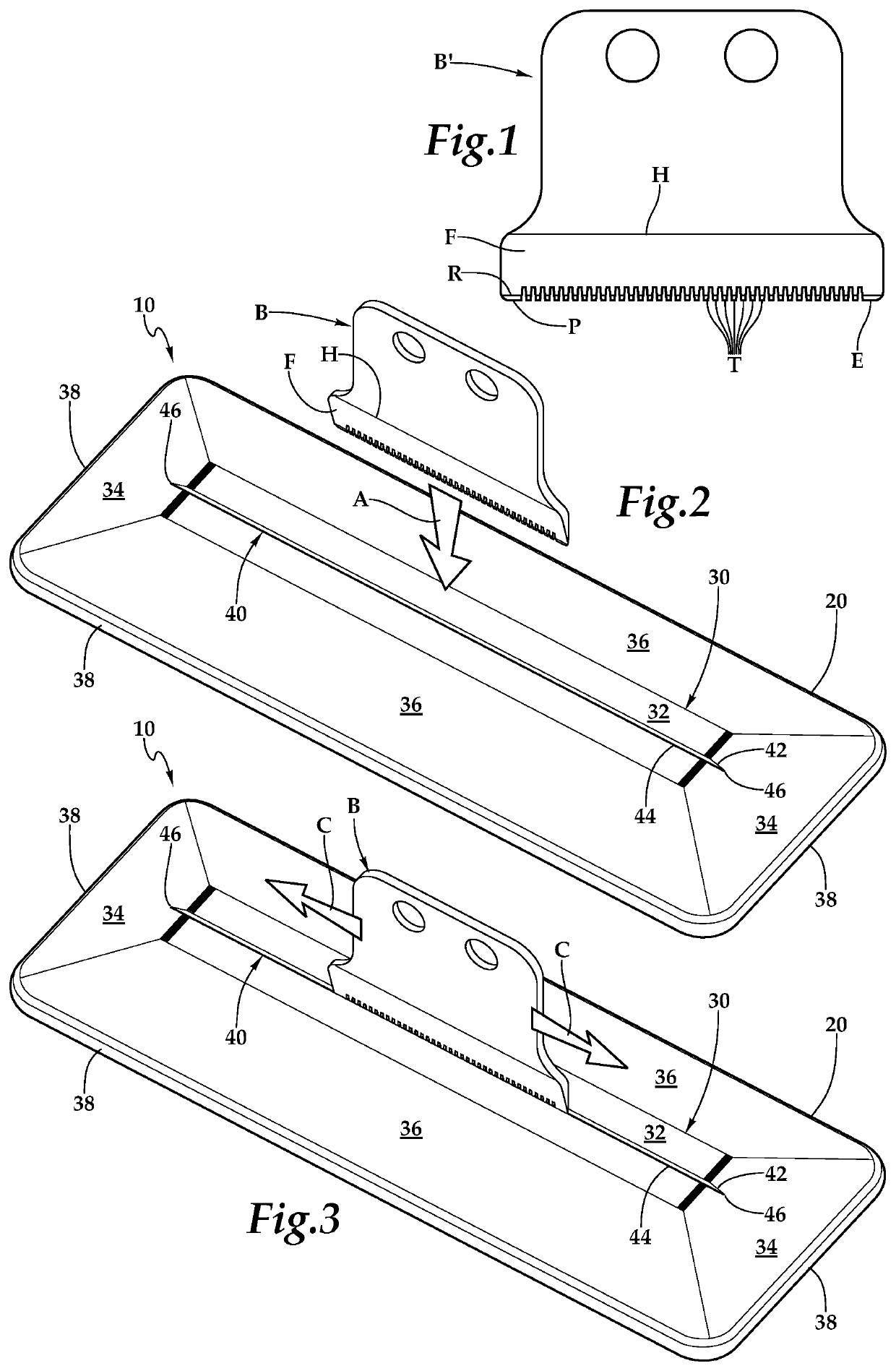
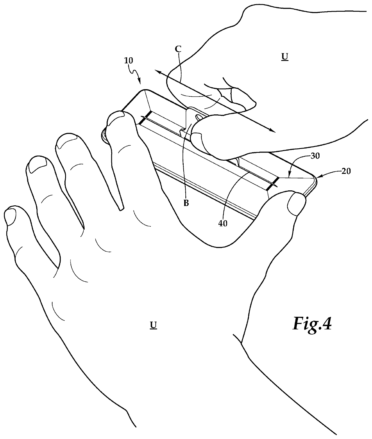
[0029]Referring to the drawings, wherein like reference numerals represent like parts throughout the various drawing figures, reference numeral 10 is directed to a modifier for a trimmer blade B. The modifier 10 includes a grinder such as in the form of a grinding stone 60 held within a base 20 to facilitate forming of a face E adjacent to a tip P of the blade B and closer to the tip P then a facet F adjacent to the face E. The modifier 10 forms the face E at a face angle β which is greater than a facet angle α of the facet on the blade B.

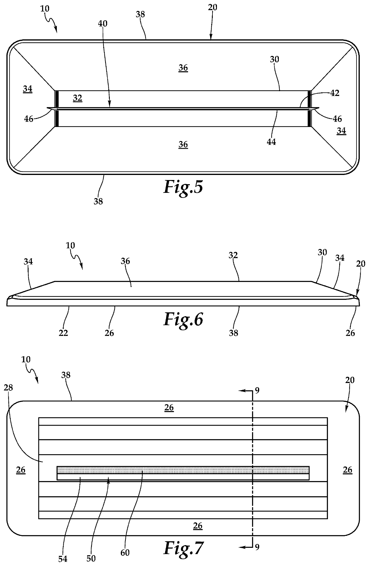
[0030]In essence, and with particular reference to FIGS. 2-7, 9 and 11, basic details of the modifier 10 are described, according to an exemplary embodiment. The modifier 10 includes a base 20 supporting a grinding stone 60 therein. The base 20 includes the top surface 30 with a slit 40 extending therethrough. A slot 50 is formed in an undersurface 22 of the base 20 with the slot 50 sized to receive the stone 60 therein. The slot 50 is oriented so ...


PUM

PropertyMeasurementUnit
Angleaaaaaaaaaa
Widthaaaaaaaaaa
Dimensionaaaaaaaaaa

Abstract

A base includes a top surface with an elongate slit formed therein. A grinder, such as in the form of a grinding stone, is located within the base and beneath the slit. The stone is in a slot in an undersurface opposite the top surface. The slot is angled to present a grinding surface of the grinding stone at an appropriate angle for forming a face surface in a trimmer blade at a desired angle. The slit has a flat side and an angled side to assist in having a trimmer blade held vertically and at a proper angle for forming of the face. The base includes a finger purchase area to hold the base adjacent to an underlying surface for stability while moving a trimmer blade within the slit adjacent to the grinding surface to form the face at the desired face angle adjacent to the trimmer blade tip.

Description

CROSS-REFERENCE TO RELATED APPLICATIONS[0001]This application claims benefit under Title 35, United States Code § 119(e) of U.S. Provisional Application No. 62 / 421,075 filed on Nov. 11, 2016.FIELD OF THE INVENTION[0002]The following invention relates to tools which can modify teeth of a cutting tool such as a trimmer blade and particularly an electric trimmer blade which includes a moving trimmer blade which moves laterally relative to a stationary trimmer blade, such as for cutting hair. More particularly, this invention relates to blade modifiers which are configured to grind a face adjacent to a tip of the trimmer blade with the face having a greater angle than a facet of the trimmer blade and with the face closer to the tip of the trimmer blade then the facet of the trimmer blade.BACKGROUND OF THE INVENTION[0003]Trimmers are known in the prior art for cutting hair and other items. Such trimmers are often powered, such as by an electric motor, and configured to be a handheld tool...

Claims


Application Information

Patent Timeline
IPC IPC(8): B24B3/36B24D15/06B26B19/38
CPCB26B19/3846B24D15/06
Inventor TORRES, CHUKA A.
Owner TORRES CHUKA A
Why Eureka
Try Eureka