Ink-jet printer

a technology of inkjet printer and inkjet printing, which is applied in the direction of printing, other printing apparatus, etc., can solve the problems of reducing the execution time of each of the respective processing components of preparing processing, and accumulating small or slight load in the electronic circuit. , to achieve the effect of prolonging reducing the execution time of the flushing processing, and reducing the l a technology of the execution time of the execution time of the execution time of the execution time of the execution time of the execution time of the execution time of the execution time of the execution time of the execution time of the execution time of the execution time of the execution time of the execution time of the execution time of the execution time of the execution time of the execution time of the execution time of the a printer and the effect of the execution time of the a printer and the effect of the execution time the effect of the preparing the processing

Active Publication Date: 2020-02-18
BROTHER KOGYO KK
View PDF12 Cites 0 Cited by
  • Summary
  • Abstract
  • Description
  • Claims
  • Application Information

AI Technical Summary

Benefits of technology

[0006]The present teaching has been made in view of the above-described situation, and an object of the present teaching is to provide an ink-jet printer capable of shortening the FPOT while reducing the load on the constitutive elements or parts of the ink-jet printer.
[0008]In the ink-jet printer having the above-described configuration, the FPOT is affected by whichever ends later among a first processing group (for example, a voltage boosting processing and a flushing processing, to be described later on) which are executed in series and another second processing group (for example, a drive switching processing and an initial conveying processing, to be described later on) which are executed in series. Further, there is such a tendency that the execution time of the flushing processing becomes longer as the ink amount by which the recording head is allowed to jet the ink is greater. In view of this, as in the above-described configuration, provided that the execution time of the second processing group (for example, drive switching processing and the initial conveying processing) is a fixed value, the execution time of the voltage boosting processing is made to be shorter as the execution time of the flushing processing becomes longer. As a result, the difference in the completion time (finish time) between the two processing groups which are executed in parallel becomes small, thereby making it possible to suppress the increase in the FPOT.
[0009]Note that the second voltage boosting pattern is not such a pattern by which the driving voltage is boosted rapidly to such an extent that any large load is applied on an electronic circuit configured to boost the voltage of the electric power supply. If, however, the voltage boosting processing in accordance with the second voltage boosting pattern is repeatedly executed, any small or slight load is consequently accumulated in the electronic circuit. In view of this, in a case that the execution time of the flushing is short, the first voltage boosting pattern in which the driving voltage is boosted in the relatively long voltage boosting time is used, thereby making it possible to reduce the load which would have otherwise accumulated in the electronic circuit.
[0011]In the ink-jet printer having the above-described configuration, the FPOT is affected by whichever ends later among a first processing group (for example, the voltage boosting processing and the flushing processing, to be described later on) which are executed in series and another second processing group (for example, the drive switching processing and the initial conveying processing, to be described later on) which are executed in series. Further, there is such a tendency that the execution time of the flushing processing becomes longer as the ink amount by which the recording head is allowed to jet the ink is greater. In view of this, as in the above-described configuration, provided that the execution time of the second processing group (for example, drive switching processing and the initial conveying processing) is a fixed value, the execution time of the voltage boosting processing is made to be shorter as the execution time of the flushing processing becomes longer. As a result, the difference in the completion time (finish time) between the two processing groups which are executed in parallel becomes small, thereby making it possible to suppress the increase in the FPOT.
[0012]Note that the rotating of the motor in the normal and reverse directions (performing normal and reverse rotations of the motor; hereinafter referred to as a “jiggling”) is executed for meshing the first and second gears with each other appropriately. Further, the first and second gears are meshed with each other appropriately by the jiggling performed for the second number of times. However, in a case that an attempt is made to mesh the first and second gears with each other with the jiggling performed for a small number of times, any slight load is consequently accumulated in each of the gears. In view of this, in a case that the execution time of the flushing processing is long, it is possible to reduce the load which would have otherwise accumulated in the gears by performing the jiggling for the first number of times, which is greater than the second number of times.

Problems solved by technology

Accordingly, simply reducing the execution time of each of the respective processings composing the preparing processing would not be appropriate or suitable.
Further, there is such a tendency that the execution time of the flushing processing becomes longer as the ink amount by which the recording head is allowed to jet the ink is greater.
If, however, the voltage boosting processing in accordance with the second voltage boosting pattern is repeatedly executed, any small or slight load is consequently accumulated in the electronic circuit.
Further, there is such a tendency that the execution time of the flushing processing becomes longer as the ink amount by which the recording head is allowed to jet the ink is greater.

Method used


Image

  • Ink-jet printer
  • Ink-jet printer
  • Ink-jet printer

Examples


Embodiment Construction

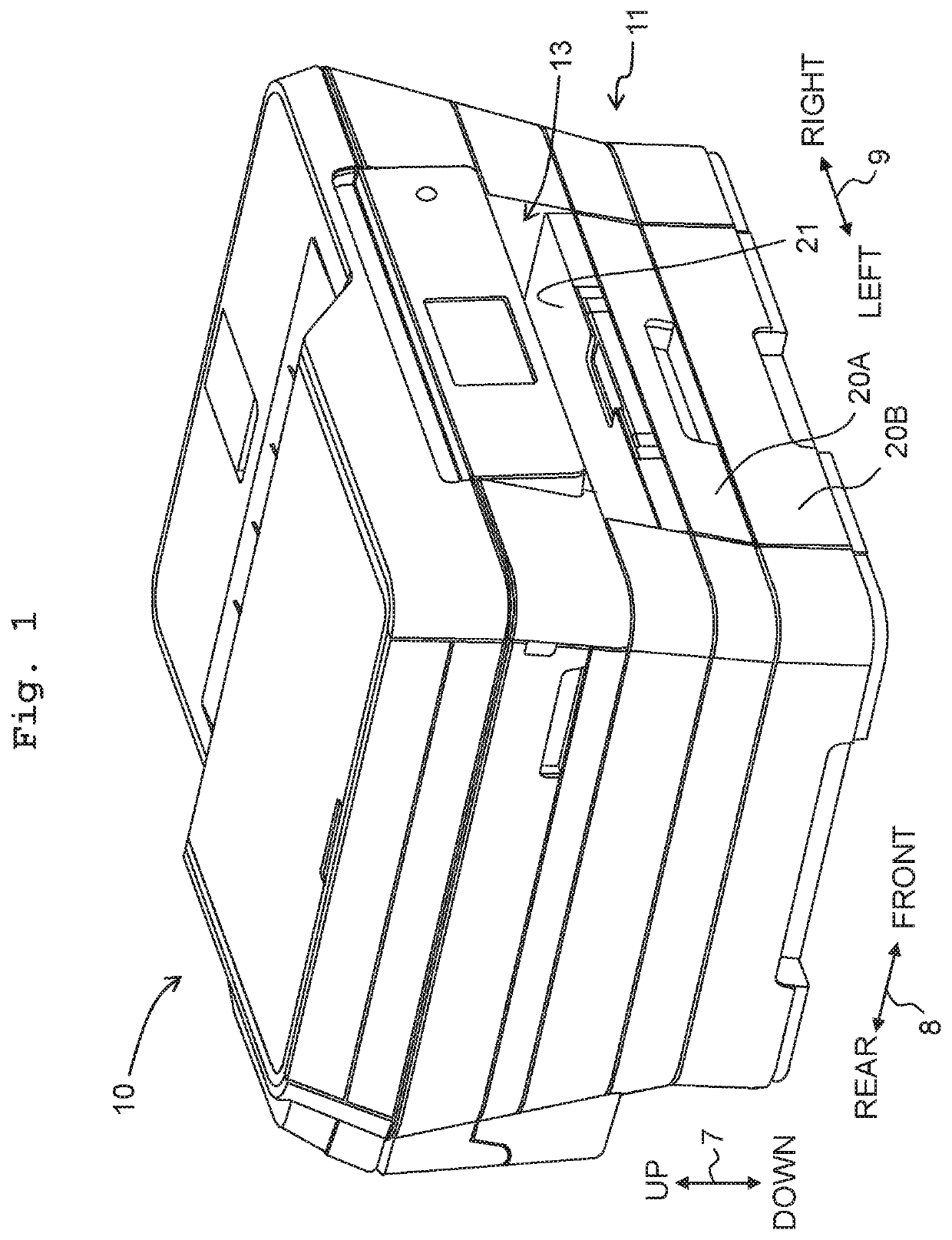
[0026]In the following, an embodiment of the present teaching will be explained, with reference to the drawings. Note that, however, the embodiment explained below is merely an example of the present teaching; it goes without saying that it is possible to make any appropriate change(s) in the embodiment of the present teaching without departing from the gist and / or scope of the present teaching. Further, in the following explanation, advancement (movement) from a starting point to an end point of an arrow is expressed as an “orientation” and coming and going on a line connecting the starting point and the end point of the arrow is expressed as a “direction”. Furthermore, in the following explanation, an up-down direction 7 is defined with a state in which a multi-function peripheral 10 is usably installed (a usable state; a state depicted in FIG. 1), as the reference; a front-rear direction 8 is defined, with a side on which an opening 13 of the multi-function peripheral 10 is provi...


PUM


Abstract

There is provided an ink-jet printer comprising: a recording head, an electric power supply, and a controller which is configured: to determine an ink amount in which an ink is jetted by the recording head in a flushing processing; in a case that the determined ink amount is less than a first ink amount, to boost a driving voltage of the electric power supply to a target voltage value, in accordance with a predetermined first voltage boosting pattern; and in a case that the determined ink amount is not less than the first ink amount, to boost the driving voltage to the target voltage value, in accordance with a predetermined second voltage boosting pattern in which a voltage boosting time is shorter than that in the first voltage boosting pattern. Accordingly, it is possible to shorten FPOT while reducing the load on the constitutive elements of the ink-jet printer.

Description

CROSS REFERENCE TO RELATED APPLICATION[0001]The present application claims priority from Japanese Patent Application No. 2017-064560 filed on Mar. 29, 2017 the disclosure of which is incorporated herein by reference in its entirety.BACKGROUNDField of the Invention[0002]The present invention relates to an ink-jet printer configured to record an image, etc., on a sheet.Description of the Related Art[0003]Conventionally, an attempt is made, in an information processing apparatus and a printer which are connected to each other via a communication network, to shorten FPOT (abbreviation of First Print Out Time) that is a time since a print instruction or command is input to the information processing apparatus (terminal) until a first sheet is discharged from the printer. Further, as one of the methods for shortening the FPOT, it is considered to shorten the time for a preparing processing.[0004]The preparing processing is a processing that the printer should execute before the printer re...

Claims


Application Information

Patent Timeline
Patent Type & Authority Patents(United States)
IPC IPC(8): B41J2/045B41J2/17B41J13/00B41J11/00
CPCB41J2/1707B41J13/0009B41J2/04573B41J2/04541B41J11/0095B41J2/04581B41J13/0027B41J29/13B41J29/38B41J2/16508B41J2/16517
Inventor ARAKANE, SATORU
Owner BROTHER KOGYO KK
Why Eureka
Try Eureka