Valve control device

a valve and control device technology, applied in the direction of valve operating means/releasing devices, valves, mechanical equipment, etc., can solve the problems of not being able to adjust the transmitted torque, not being able to adapt the torque to the operational requirement, and not being able to meet the operational requirement. , to achieve the effect of reducing the response time, reducing costs, and simplifying the production and mounting of the rack

Active Publication Date: 2020-02-18
4MC
View PDF16 Cites 0 Cited by
  • Summary
  • Abstract
  • Description
  • Claims
  • Application Information

AI Technical Summary

Benefits of technology

[0022]This will thus make it possible to drive the opening and / or closing of valves by providing a varying rotation speed.
[0023]In order to limit costs, minimize the response time and simplify the production and mounting of the rack, it is also recommended that this step should include:

Problems solved by technology

These two families are set: once the devices are manufactured and mounted in their casings, no adjustment of the transmitted torque is possible, with the risk of unsuitability to the operational requirements.
A problem remains however as to the adaptation of the torque to the operational requirement to be met.

Method used


Image

  • Valve control device
  • Valve control device
  • Valve control device

Examples


Embodiment Construction

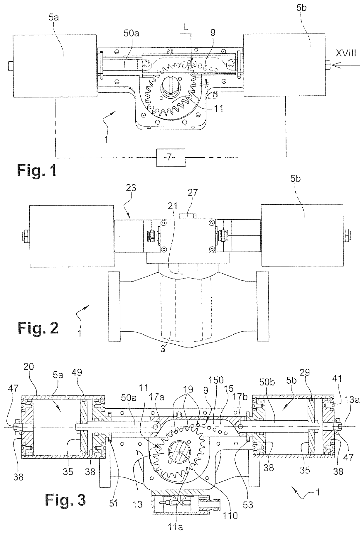
[0058]FIGS. 1-4 in particular show that the illustrated device 1 is used for actuating, between two positions, a member 3, such as a valve to be closed and opened, from at least one actuator, such as 5a, 5b, such as a piston / cylinder, controlled by at least one power source 7 (shown only in FIG. 1).

[0059]The power source(s) 7 may be a pneumatic source, such as a source of compressed air, and / or a hydraulic source or, for one source if there are several ones, return means such as a spring.

[0060]FIGS. 2 and 3 illustrate a valve 3, which is shown in dotted lines when closed and in mixed lines when opened.

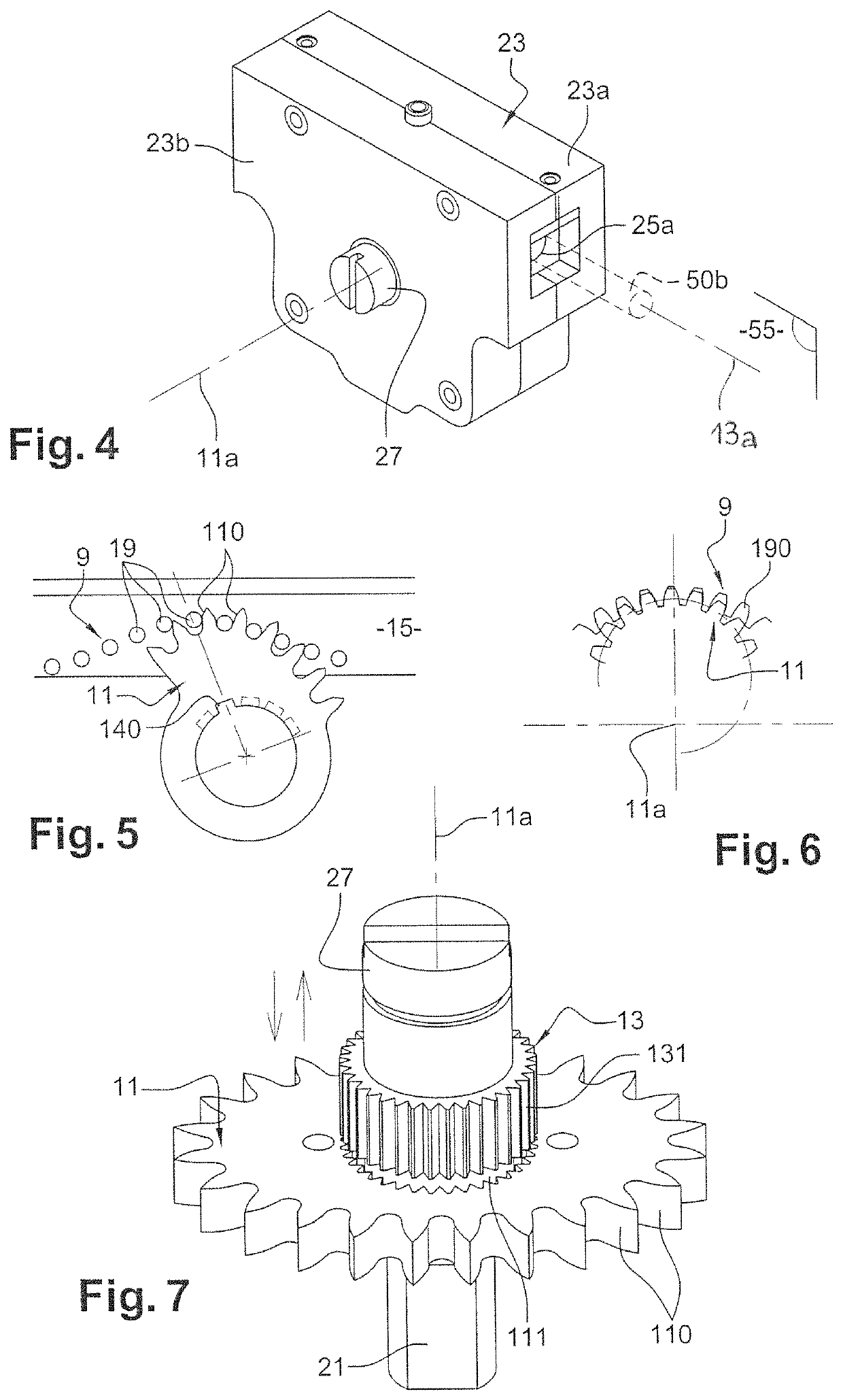
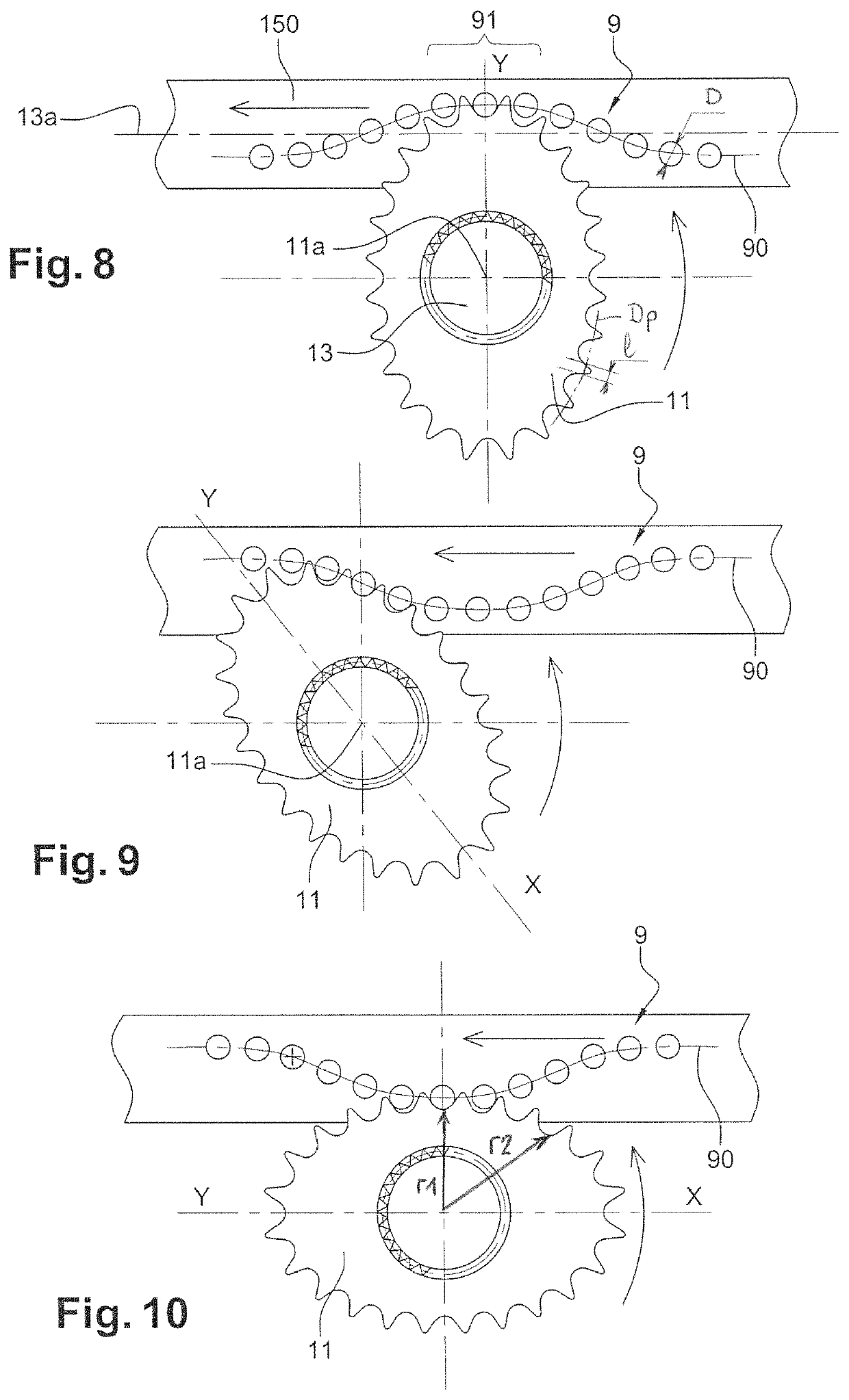
[0061]The valve 3 is actuated by a rack 9 which can engage with a toothed rotating pinion 11 the teeth of which, which develop according to a primitive perimeter, are located at several different radii.

[0062]Such radii determine the minimum and maximum available torques.

[0063]The pinion 11 has an elliptical section, as illustrated in FIG. 3.

[0064]The rack 9 globally extends (i.e. withi...


PUM


Abstract

A device for actuating a valve by means of a rack meshing with an elliptical pinion connected with a sleeve so that one transmits a torque to the other. The connections between the pinion and the rack as well as the sleeve are separable, so that the angular reference positions of the pinion relative to both the rack and the sleeve can be adapted according to a predefined variation in the torque required for actuating the valve.

Description

FIELD OF THE INVENTION[0001]The present invention relates to a solution for transforming a longitudinal force into a torque actuating a mechanical member, such as a tap or a valve, within the torque variations thereof. This solution applies to any mechanism requiring rotation with a variable torque.[0002]More precisely, the solution disclosed here relates to:[0003]a method both for preparing and performing the actuating of a member between two positions, such as a valve to be closed and opened,[0004]and the corresponding actuating device.BACKGROUND OF THE INVENTION[0005]At least two actuators families, one based on the rack-and-pinion principle and the other based on the lever arm (“Scotch yoke”) principle are known.[0006]These two families are set: once the devices are manufactured and mounted in their casings, no adjustment of the transmitted torque is possible, with the risk of unsuitability to the operational requirements.[0007]In the rack-and-pinion case, the torque is constant...

Claims


Application Information

Patent Timeline
Patent Type & Authority Patents(United States)
IPC IPC(8): F16K31/53F15B15/06F16K31/54F16K31/163F16H19/04F15B21/00
CPCF15B15/065F16H19/04F16K31/1635F16K31/54F15B21/003F16K31/535
Inventor MOLINARO, NARCISO LORIS
Owner 4MC
Why Eureka
Try Eureka