Light-emitting diode chip and micro display device

a technology of light-emitting diodes and micro-displays, which is applied in the direction of semiconductor devices, instruments, electrical apparatus, etc., can solve the problems of increasing steps and process times, difficult to improve process precision and yield, and relatively complicated transfer process, so as to reduce the number of transfer processes and process time, the effect of simplifying the driver circui

Active Publication Date: 2020-02-18
LG DISPLAY CO LTD
View PDF23 Cites 1 Cited by
  • Summary
  • Abstract
  • Description
  • Claims
  • Application Information

AI Technical Summary

Benefits of technology

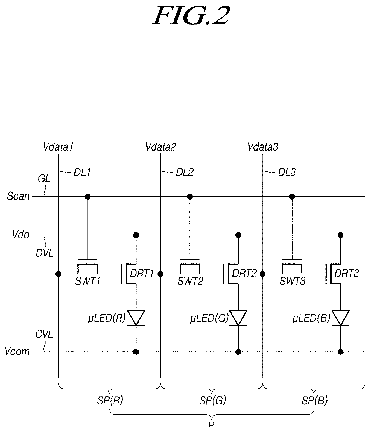
[0014]An aspect of the present disclosure is provide a μLED capable of producing all light of red, green, and blue with improved process efficiency and having a simplified driver circuit for driving the μLED.
[0015]Another aspect of the present disclosure is provide a μLED implemented with improved process precision and reduced defects through an improved transfer process.
[0021]According to exemplary embodiments, the μLED capable of producing all of red, green, and blue light can be easily implemented by regrowing a green light-producing section on a blue light-producing wafer. Further, with the μLED implemented based on blue and green light having a similar driving voltage, the driver circuit can be simplified.
[0022]According to exemplary embodiments, all of red, green, and blue light can be produced using a single μLED chip, thereby reducing the number of transfer processes and process time required for the μLED and improving the precision and yield of the process.

Problems solved by technology

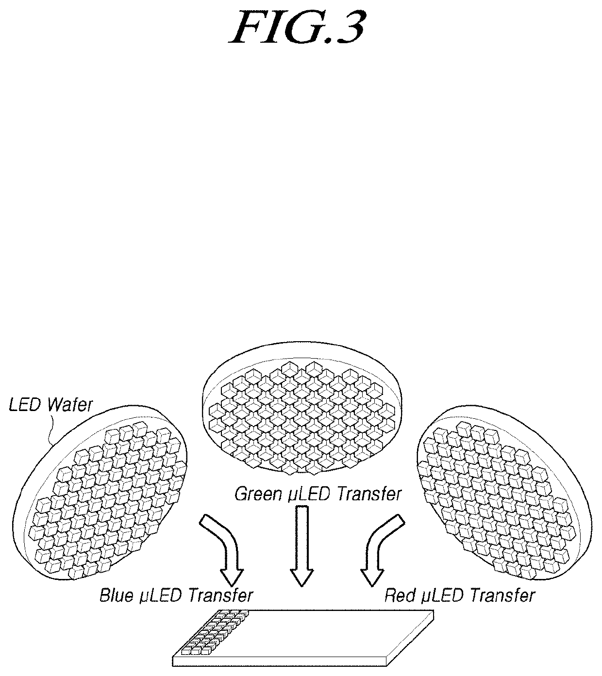
When the μLED is implemented using such a transfer method, there is a problem in that the μLED is very small, so the transfer process may be relatively complicated, being difficult to improve precision and yield of the process.
Further, since for production of light, the transfer process is performed after μLEDs for red (R) light, green (G) light, and blue (B) light, respectively, are grown, the number of transfer steps and process times increase, causing increased defects due to misalignments, which are problematic.

Method used


Image

  • Light-emitting diode chip and micro display device
  • Light-emitting diode chip and micro display device
  • Light-emitting diode chip and micro display device

Examples


Embodiment Construction

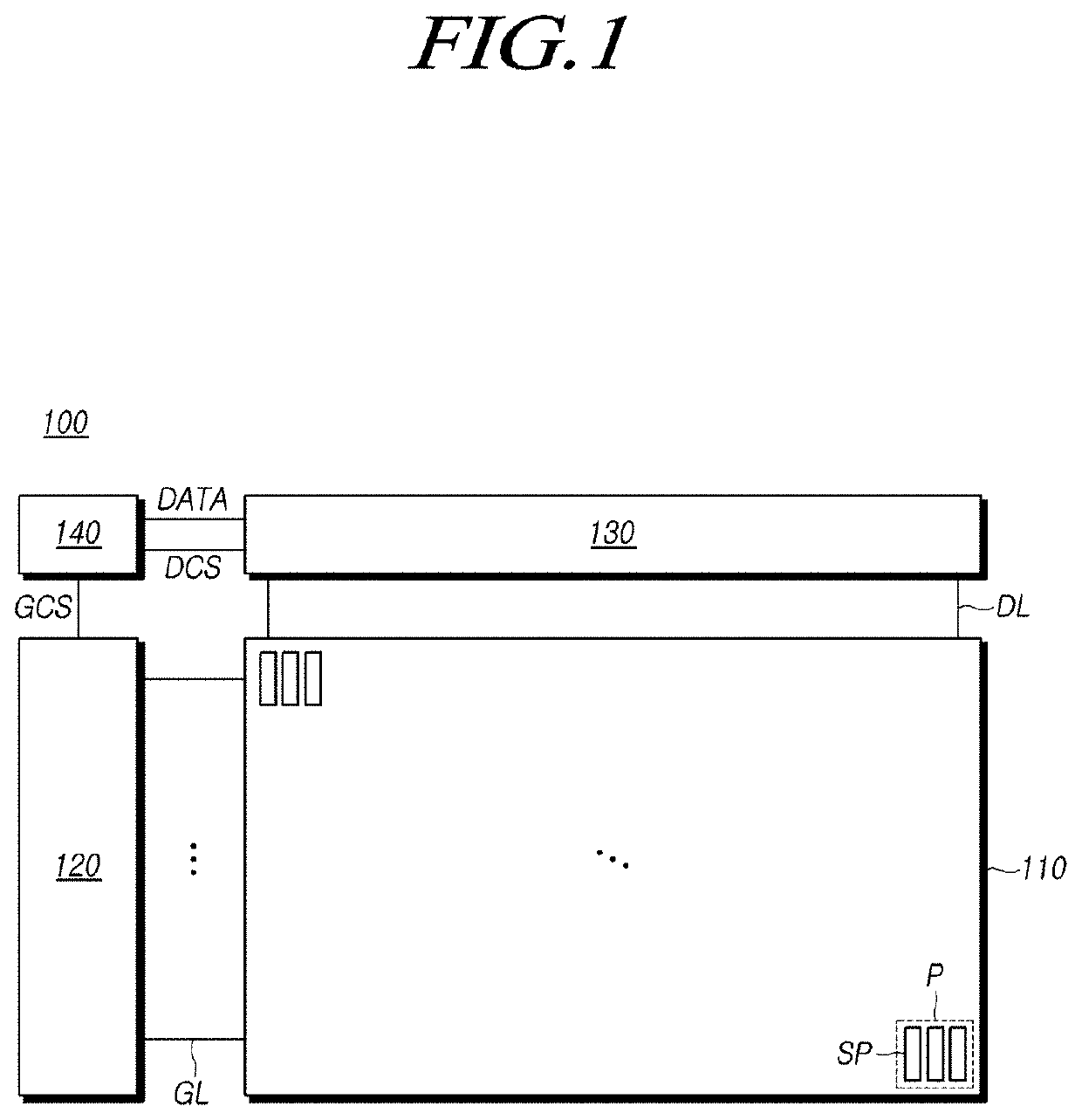
[0035]Hereinafter, reference will be made to embodiments of the present disclosure, examples of which are illustrated in the accompanying drawings. Throughout this document, reference should be made to the drawings, in which the same reference numerals and symbols will be used to designate the same or like components. In the following description of the present disclosure, detailed descriptions of known functions and components incorporated herein will be omitted in the case that the subject matter of the present disclosure may be rendered unclear thereby.

[0036]It will also be understood that, while terms such as “first,”“second,”“A,”“B,”“(a),” and “(b)” may be used herein to describe various elements, such terms are merely used to distinguish one element from other elements. The substance, sequence, order, or number of these elements is not limited by these terms. It will be understood that when an element is referred to as being “connected to” or “coupled to” another element, not ...


PUM

PropertyMeasurementUnit
driving voltageaaaaaaaaaa
first wavelength bandaaaaaaaaaa

Abstract

A light-emitting diode (LED) chip and a display device having the same are provided. A green LED is regrown on a blue LED to produce blue and green light, and a red phosphor is disposed on the blue or green LED to produce red light. Red light, green light, and blue light are to be produced using a single LED chip. The single LED chip forms three subpixels therein so as to facilitate a transfer process of the LED chip to a display panel. The LED chip is configured based on the blue, green, and blue LEDs so as to facilitate the fabrication and driving of the LED chip.

Description

CROSS REFERENCE TO RELATED APPLICATION[0001]This application claims priority from Korean Patent Application No. 10-2017-0172248, filed on Dec. 14, 2017, which is hereby incorporated by reference for all purposes as if fully set forth herein.BACKGROUNDTechnical Field[0002]The present disclosure relates to a light-emitting diode chip and a micro display device.Description of Related Art[0003]In response to the development of the information society, there has been increasing demand for display devices able to display images. Recently, a range of display devices, such as liquid crystal display (LCD) devices, plasma display devices, and organic light-emitting display devices, have come into widespread use.[0004]Such display devices may include a display panel having a plurality of subpixels and a variety of driver circuits, such as a gate driver circuit, a data driver circuit, and the like, for driving the display panel.[0005]In a display device of the related art, a display panel is co...

Claims


Application Information

Patent Timeline
Patent Type & Authority Patents(United States)
IPC IPC(8): H01L27/15H01L25/18H01L33/50G09G3/3225H01L33/44H01L33/00H01L27/12G09G3/32H01L25/075
CPCH01L33/508G09G3/3225H01L25/18H01L33/007H01L27/15H01L33/44H01L25/0753G09G3/32H01L27/1214H01L33/50H01L33/62H01L33/20H01L27/156H01L33/36H01L33/48H01L33/58
Inventor KWAK, YONGSEOKYANG, KIYONGMOON, JINSUSEO, MYUNGWON
Owner LG DISPLAY CO LTD
Why Eureka
Try Eureka