Transmission filter

Active Publication Date: 2020-02-25
FORD GLOBAL TECH LLC
View PDF6 Cites 2 Cited by
  • Summary
  • Abstract
  • Description
  • Claims
  • Application Information

AI Technical Summary

Benefits of technology

A transmission includes a filter housing, a baffle, and a valve. The filter housing contains filter media and defines an inlet. The baffle defines front and rear openings. The baffle may be fixed to the filter housing. The valve is located within the baffle. The baffle may include a front bulkhead between the front opening and the inlet and a rear bulkhead between the rear opening and the inlet. The valve is configured to prevent air ingestion into the inlet. Specifically, the valve prevents flow from the front opening to the inlet in response to weight of fluid on a front side of the valve when the front opening is elevated relative to the rear opening. The valve also prevents flow from the rear opening to the

Problems solved by technology

When the fluid contains contaminants, it may be less effective

Method used


Image

  • Transmission filter
  • Transmission filter
  • Transmission filter

Examples


Embodiment Construction

Embodiments of the present disclosure are described herein. It is to be understood, however, that the disclosed embodiments are merely examples and other embodiments can take various and alternative forms. The figures are not necessarily to scale; some features could be exaggerated or minimized to show details of particular components. Therefore, specific structural and functional details disclosed herein are not to be interpreted as limiting, but merely as a representative basis for teaching one skilled in the art to variously employ the present invention. As those of ordinary skill in the art will understand, various features illustrated and described with reference to any one of the figures can be combined with features illustrated in one or more other figures to produce embodiments that are not explicitly illustrated or described. The combinations of features illustrated provide representative embodiments for typical applications. Various combinations and modifications of the fe...


PUM

PropertyMeasurementUnit
Weightaaaaaaaaaa
Flow rateaaaaaaaaaa
Transmissionaaaaaaaaaa

Abstract

A transmission filter includes a baffle with a valve. The baffle defines front and rear openings. When a vehicle climbs or descends a hill, the valve moves in response to the weight of fluid on a higher side of the baffle. The valve prevents flow from the higher of the front and rear openings preventing air ingestion into the filter.

Description

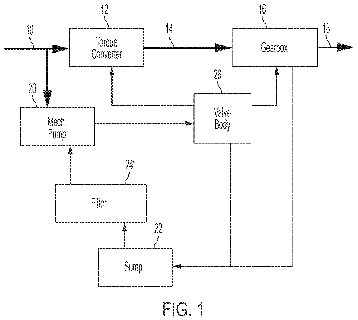
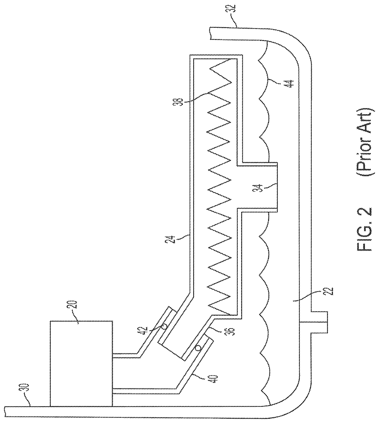
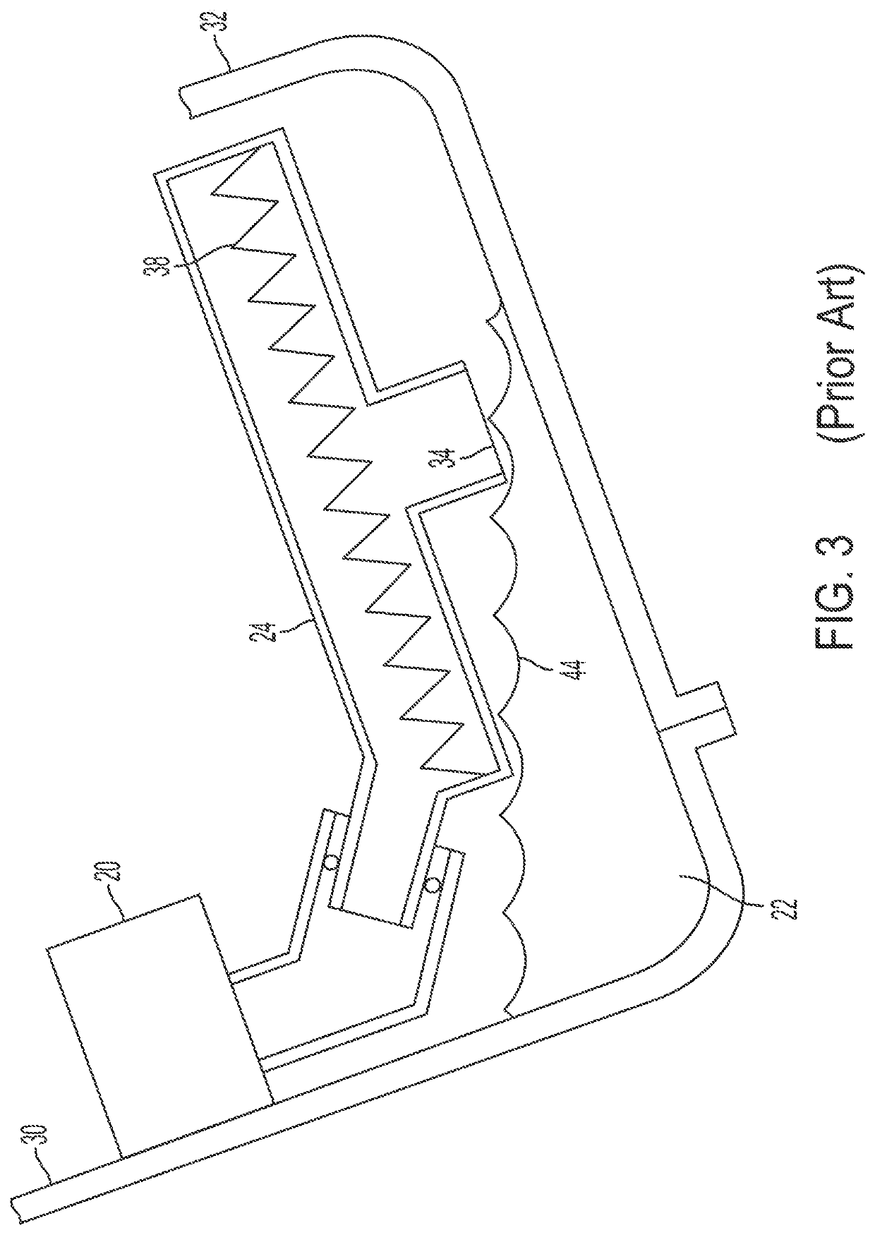
TECHNICAL FIELDThis disclosure relates to the field of transmission systems. More particularly, the disclosure pertains to a transmission filter designed to prevent air ingestion when a vehicle is accelerating, decelerating, or on a grade.BACKGROUNDAutomatic transmission fluid serves many functions in a modem automatic transmission. Pressurized fluid may be used to engage friction clutches in order to establish a power flow path with a desired speed ratio. Fluid lubricates gears and bearings. Excess heat is removed by fluid flowing over various components. When the fluid contains contaminants, it may be less effective in these functions and may cause failures such as stuck valves. Therefore, transmissions often include fluid filters. The fluid typically drains to a sump due to gravity. A transmission pump draws fluid from the sump and delivers pressurized fluid to a valve body, which distributes the fluid to various places within the transmission at pressures appropriate to the vari...

Claims


Application Information

Patent Timeline
IPC IPC(8): B01D35/153F16H57/04B01D35/157B01D35/00
CPCF16H57/0404F16H57/0443B01D35/1573B01D35/005B01D35/153F16H41/30F16H57/0435B01D35/0273F16H57/04
Inventor YASNOGORODSKIY, VLADIMIRAESCHLIMAN, DAVID P.
Owner FORD GLOBAL TECH LLC
Why Eureka
Try Eureka