
Grommet and grommet-equipped wire harness

a technology of wire harnesses and grommets, which is applied in the direction of insulated conductors, cables, conductors, etc., can solve the problems of reducing the holding force of grommets, difficult to achieve both a reduction of the insertion force of grommets and an increase in the force with which the attachment hole holds the grommets, etc., to achieve a small holding force, minimize the force needed, and reduce the effect of insertion for

Active Publication Date: 2020-02-25
SUMITOMO WIRING SYST LTD
View PDF36 Cites 1 Cited by
  • Summary
  • Abstract
  • Description
  • Claims
  • Application Information

AI Technical Summary

Benefits of technology

This design allows for easy insertion with reduced force and maximizes holding force, improving water sealing and preventing grommet displacement, while maintaining a thin profile for easier deformation and installation.

Problems solved by technology

Upon doing so, there is a risk that the holding force of the grommet will decrease in a state in which the grommet is attached to the attachment hole.
For this reason, it has been difficult to achieve both a reduction of the insertion force of the grommet and an increase in the force with which the attachment hole holds the grommet.

Method used


Image

  • Grommet and grommet-equipped wire harness
  • Grommet and grommet-equipped wire harness
  • Grommet and grommet-equipped wire harness

Examples


modified examples

In the above-described embodiment, a configuration in which the ring-shaped portion 54 is pressed to the inner circumferential edge portion 13 of the attachment hole 12 by the inner member 60 and a configuration in which the ring-shaped portion 54 is elastically deformed so as to protrude significantly by the inner member-side locking protrusion 66 and the portion 54p is locked onto the circumferential edge portion of the attachment hole 12 from the one surface side of the panel 10 were both employed, but it is also possible to employ only one of the two configurations.

Also, as shown in FIG. 17, in a state before elastic deformation, the temporary locking protrusion 100 that locks onto the circumferential edge portion of the attachment hole 12 from the one surface side of the panel 10 may be formed at the portion of the ring-shaped portion 54 that is elastically deformed by the inner member-side locking protrusion 66. The temporary locking protrusion 100 may be provided in a ring sh...


PUM

PropertyMeasurementUnit
elasticaaaaaaaaaa
diameteraaaaaaaaaa
elastic deformationaaaaaaaaaa

Abstract

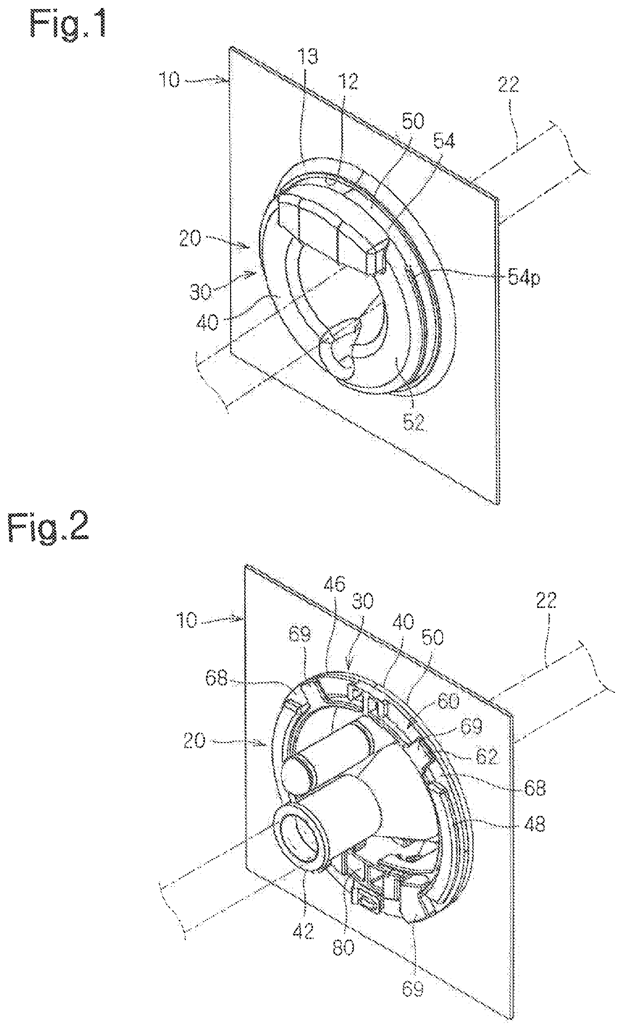
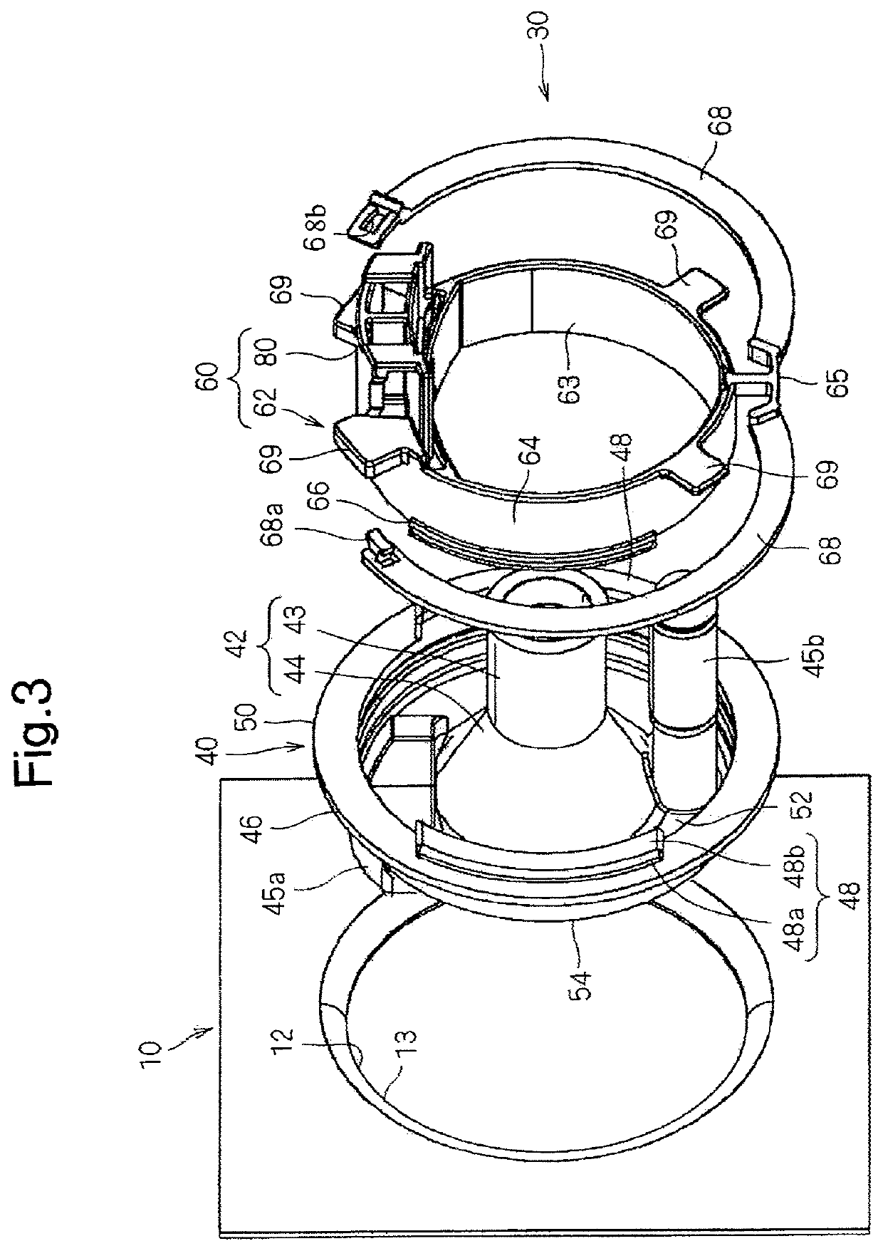
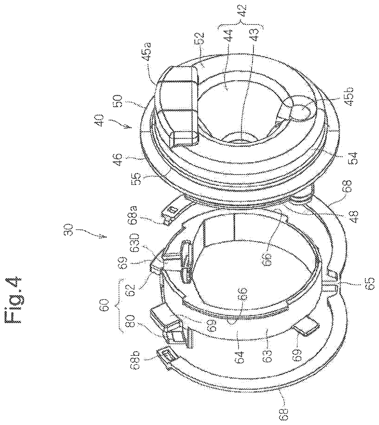
A grommet includes a grommet main body made of an elastic material and an inner member. The grommet main body includes a cylinder portion and a large diameter portion that is formed so as to extend toward the outer circumference side from the cylinder portion, a ring-shaped portion that can be arranged on the inner circumference side of the attachment hole being formed on the outer circumferential portion. The grommet main body is fit into the attachment hole from one end side in the attachment direction of the large diameter portion.

Description

TECHNICAL FIELDThe present invention relates to a grommet to be equipped on a portion of a wire harness that is to be inserted through a through hole of a vehicle body panel.BACKGROUND ARTPatent Document 1 discloses a grommet that is to be attached to an attachment hole formed in a panel, the grommet including a cylinder portion provided with a through hole through which a wire harness is to be inserted, and a diameter expansion portion that is formed so as to extend outward from the cylinder portion, the outer circumferential portion of the diameter expansion portion being provided with a ring-shaped groove into which a circumferential edge portion of the attachment hole can be fit.CITATION LISTPatent DocumentsPatent Document 1: JP 2015-186399ASUMMARY OF INVENTIONProblem to be SolvedWith the grommet disclosed in Patent Document 1, when the grommet is inserted into the attachment hole formed in the panel, the diameter expansion portion needs to be pressed into the circumferential ed...

Claims


Application Information

Patent Timeline
Patent Type & Authority Patents(United States)
IPC IPC(8): H02G3/22B60R16/02F16B21/18H01B7/00H01B17/26
CPCF16B21/183B60R16/0222H01B17/26H01B7/0045H02G3/22
Inventor OKUHARA, TAKASHI
Owner SUMITOMO WIRING SYST LTD
Learn More