Control apparatus for hybrid vehicle

a control apparatus and hybrid technology, applied in the direction of engine-driven generator propulsion, transportation and packaging, propulsion parts, etc., can solve the problems of unintentional reduction of compensating torque, inability to output appropriate compensating torque, and inability to appropriately suppress torque pulsation, etc., to suppress the influence of internal combustion engine torque fluctuation

Active Publication Date: 2020-03-03
TOYOTA JIDOSHA KK
View PDF11 Cites 0 Cited by
  • Summary
  • Abstract
  • Description
  • Claims
  • Application Information

AI Technical Summary

Benefits of technology

[0006]In view of the aforementioned problems, it is therefore an object of embodiments of the present disclosure to provide a control apparatus for a hybrid vehicle that can suppress an influence of a torque fluctuation of an internal combustion engine.
[0008]According to the first control apparatus for the hybrid vehicle in the present disclosure, the calculation cycle of the pulsation compensating torque is controlled to be shorter in the period that includes the vertex portion in which the pulsation compensating torque is locally maximal or locally minimal, than that in the period that does not include the vertex portion. As a result, the pulsation compensating torque is arithmetically operated as a more accurate value in the vicinity of the vertex portion. In particular, it is possible to prevent that the pulsation compensating torque includes an unintentional frequency component due to a reduction in the torque. This makes it possible to prevent that a frequency component of the pulsation compensating torque matches a natural frequency of a mechanical system, such as a damper, and to prevent that that new vibration occurs in the hybrid vehicle.
[0009]Moreover, in embodiments of the present disclosure, it is only in the period that includes the vertex portion, that the calculation period of the damping torque is controlled to be short. It is thus possible to suppress a calculation load increase, more effectively, for example, than when the calculation period is controlled to be short all the time.
[0011]According to this aspect, in the period that includes the vertex portion, the pulsation compensating torque is arithmetically operated in a short cycle, while the torque control of the electric motor (i.e. the control of outputting the pulsation compensating torque) is performed in a relatively long cycle. It is thus possible to prevent that a reduction in the calculation period of the pulsation compensating torque causes an increase in a processing load regarding the torque control. Moreover, in the period that includes the vertex portion, the maximum value out of the plurality of pulsation compensating torques arithmetically operated (or more accurately, a value with a maximum absolute value) is outputted. Thus, the reduction in the torque can be prevented.
[0013]According to the second control apparatus for the hybrid vehicle in the present disclosure, the maximum value that can be arithmetically operated by the arithmetic operator (or more accurately, a value with a maximum absolute value) is set as the pulsation compensating torque in the period that includes the vertex portion in which the pulsation compensating torque is locally maximal or locally minimal. Thus, the reduction in the torque can be certainly prevented. It is also possible to prevent that the pulsation compensating torque includes an unintentional frequency component. Moreover, the calculation period of the pulsation compensating torque is not changed, and the calculation load is thus not increased.

Problems solved by technology

If, however, the compensating torque to be outputted has a high frequency, some calculation cycle of the compensating torque possibly does not provide sufficient time resolution, and as a result, the appropriate compensating torque cannot be outputted.
In this case, the torque pulsation cannot be appropriately suppressed.
Moreover, the compensating torque includes a frequency other than a target frequency, for example, due to an unintentional reduction in the compensating torque.
This frequency component may match a natural frequency of a damper, and that may cause new vibration.
Setting a high-frequency calculation cycle of the compensating torque all the time possibly increases a compensating torque calculation performance; however, in this case, that may cause a new problem of significantly increasing a processing load of an arithmetic operation apparatus.

Method used


Image

  • Control apparatus for hybrid vehicle
  • Control apparatus for hybrid vehicle
  • Control apparatus for hybrid vehicle

Examples


first embodiment

[0027]A control apparatus for a hybrid vehicle according to a first embodiment will be explained with reference to FIG. 1 to FIG. 6.

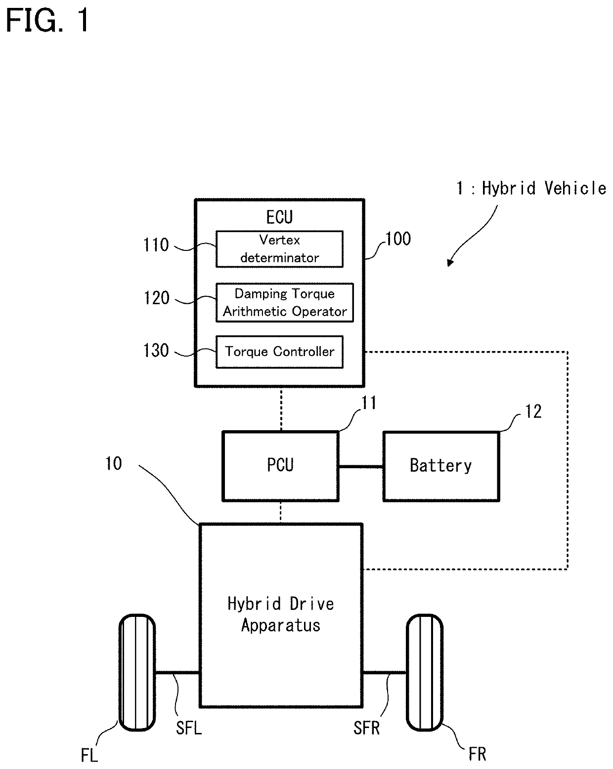
[0028]Firstly, with reference to FIG. 1, an explanation will be given to a configuration of a hybrid vehicle on which the control apparatus for the hybrid vehicle according to the first embodiment is mounted. FIG. 1 is a schematic diagram illustrating an entire configuration of the hybrid vehicle according to the first embodiment;

[0029]As illustrated in FIG. 1, a hybrid vehicle 1 according to the first embodiment is provided with an electronic control unit (ECU) 100, a power control unit (PCU) 11, a battery 12, and a hybrid drive apparatus 10.

[0030]The ECU 100 is one specific example of the “control apparatus for the hybrid vehicle”, and is provided with a central processing unit (CPU), a read only memory (ROM), a random access memory (RAM) and the like. The ECU 100 is an electronic control unit configured to control the operation of each part of the hy...

second embodiment

[0063]Next, a control apparatus for a hybrid vehicle according to a second embodiment will be explained with reference to FIG. 7 and FIG. 8. The second embodiment is different from the first embodiment only in a part of the operation, and is substantially the same as the first embodiment with regard to the other operation and the apparatus configuration. Thus, hereinafter, a different part from the first embodiment already explained will be explained in detail, and an explanation of the same part will be omitted, as occasion demands.

[0064]

[0065]The operation of the control apparatus for the hybrid vehicle according to the second embodiment will be explained in detail with reference to FIG. 7. FIG. 7 is a flowchart illustrating a flow of the operation of the control apparatus for the hybrid vehicle according to the second embodiment. In FIG. 7, the same process steps as those in the first embodiment illustrated in FIG. 4 carry the same reference numerals.

[0066]As illustrated in FIG. ...

third embodiment

[0074]Next, a control apparatus for a hybrid vehicle according to a third embodiment will be explained with reference to FIG. 9 to FIG. 11. The third embodiment is different from the first and second embodiments only in a part of the operation, and is substantially the same as the first and second embodiments with regard to the other operation and the apparatus configuration. Thus, hereinafter, a different part from the first and second embodiments already explained will be explained in detail, and an explanation of the same part will be omitted, as occasion demands.

[0075]

[0076]The operation of the control apparatus for the hybrid vehicle according to the third embodiment will be explained in detail with reference to FIG. 9. FIG. 9 is a flowchart illustrating a flow of the operation of the control apparatus for the hybrid vehicle according to the third embodiment. In FIG. 9, the same process steps as those in the first embodiment illustrated in FIG. 4 carry the same reference numera...


PUM


Abstract

A control apparatus for a hybrid vehicle is configured to control the hybrid vehicle. The control apparatus is provided with: an arithmetic operator configured to arithmetically operate a pulsation compensating torque for compensating a pulsation component; an arithmetic operation controller configured to control the arithmetic operator (i) to arithmetically operate the pulsation compensating torque in a first cycle in a period that does not include a vertex portion in which the pulsation compensating torque is locally maximal or locally minimal and (ii) to arithmetically operate the pulsation compensating torque in a second cycle, a length of which is shorter than that of the first cycle, in a period that includes the vertex portion; and a torque controller configured to control the electric motor to output a torque including the pulsation compensating torque arithmetically operated by the arithmetic operator.

Description

CROSS-REFERENCE TO RELATED APPLICATIONS[0001]This application is based upon and claims the benefit of priority of the prior Japanese Patent Application No. 2017-027210, filed on Feb. 16, 2017, the entire contents of which are incorporated herein by reference.BACKGROUND1. Technical Field[0002]Embodiments of the present disclosure relate to a control apparatus for a hybrid vehicle, configured to suppress, for example, an influence of a torque pulsation of an internal combustion engine.2. Description of the Related Art[0003]For this type of apparatus, there is known an apparatus configured to suppress a torque pulsation, which is derived from an explosion cycle of an internal combustion engine. For example, Japanese Patent Application Laid Open No. Hei 11-350997 (Patent Literature 1) proposes a technique / technology in which a torque fluctuation, which is generated on an output shaft in accordance with an inertia torque and an output torque of the internal combustion engine, is compensa...

Claims


Application Information

Patent Timeline
Patent Type & Authority Patents(United States)
IPC IPC(8): B60W10/08B60W20/15B60K6/365B60K6/445B60W30/20B60K6/22B60L50/16
CPCB60W30/20B60K6/365B60W20/15B60W10/08B60K6/22B60K6/445Y02T10/7077B60W2400/00B60W2710/085Y02T10/6239Y02T10/6286B60W2030/206B60W2710/0666B60W10/06B60W20/00B60W2710/083Y02T10/62B60W2050/0014B60W2050/005Y02T10/7072
Inventor TSUKADA, YUTAKITAZAWA, YUSUKE
Owner TOYOTA JIDOSHA KK
Why Eureka
Try Eureka