Medical image editing

a medical image and editing technology, applied in the field of medical image editing, can solve the problems that the editing process of medical images performed by trained medical personnel, such as radiologists, can become tedious, and achieve the effect of facilitating the medical image editing process

Active Publication Date: 2020-03-10
KONINKLJIJKE PHILIPS NV
View PDF28 Cites 6 Cited by
  • Summary
  • Abstract
  • Description
  • Claims
  • Application Information

AI Technical Summary

Benefits of technology

[0003]There may be a need to have an improved technique that facilitates the medical image editing process.
[0006]As an advantage, the present invention facilitates finding and picking the intended vertex of a 3D surface model, e.g. the reference vertex in the set of vertices to be transformed, by a user, e.g. medical personnel. The identification of the intended vertex is based on the detected proximity distance and the assigned ranking value. This enables a user to grab the intended vertex without great effort during editing in a 3D viewer, even when occlusion prohibits the visibility in a 3D mesh viewer. Likewise, in 2D views with contours, even when the intended vertex is not visible in the current viewing plane—but lies in front of or behind it, the user can still grab it easily. This reduces the manual effort in the interactive editing step and thus improves the workflow.

Problems solved by technology

However, to ensure accuracy and precision, especially for the medical images with low contrast, noise, and other imaging ambiguities, medical image editing as performed by trained medical personnel, such as a radiologist, can become tedious.

Method used


Image

  • Medical image editing
  • Medical image editing
  • Medical image editing

Examples


Embodiment Construction

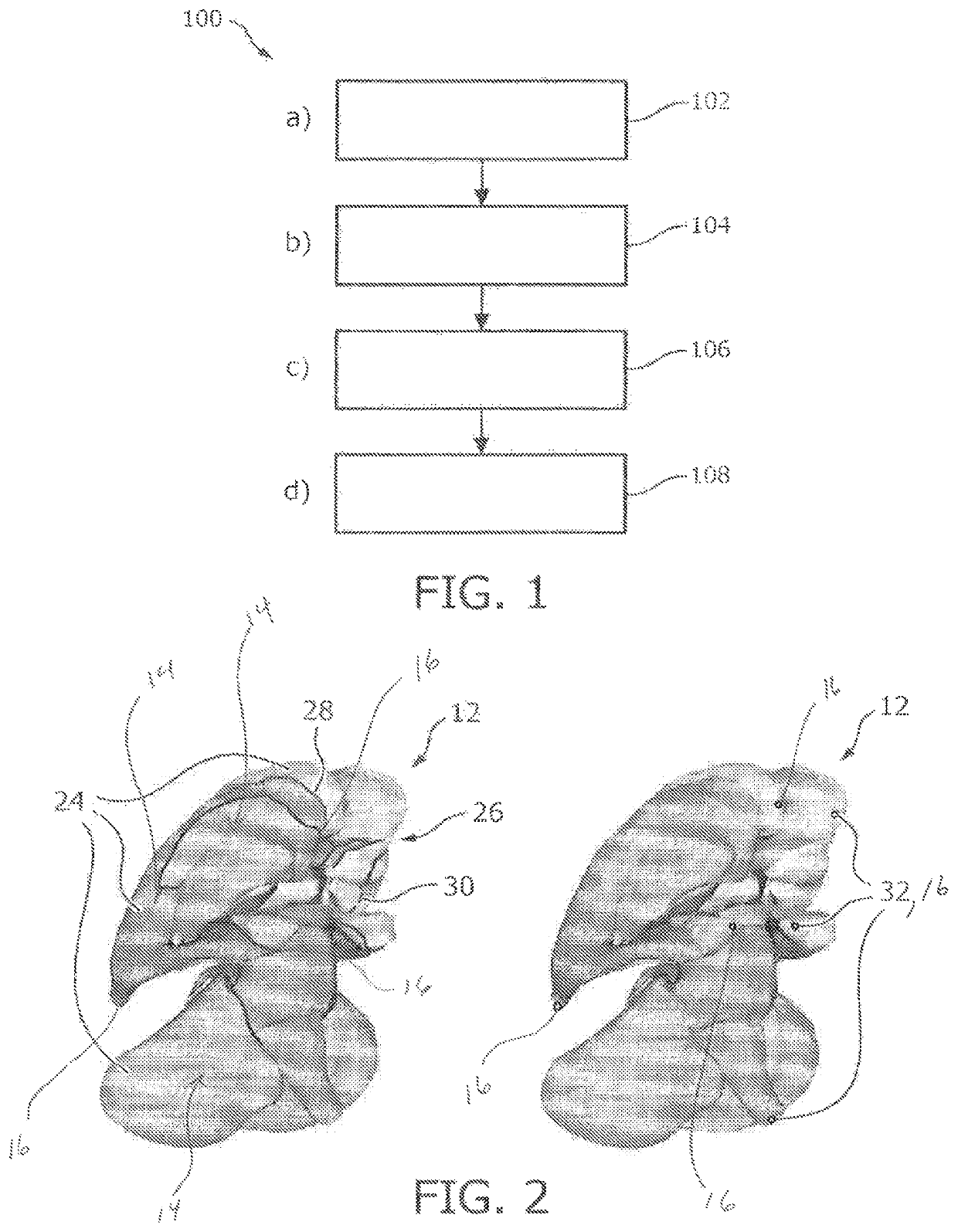
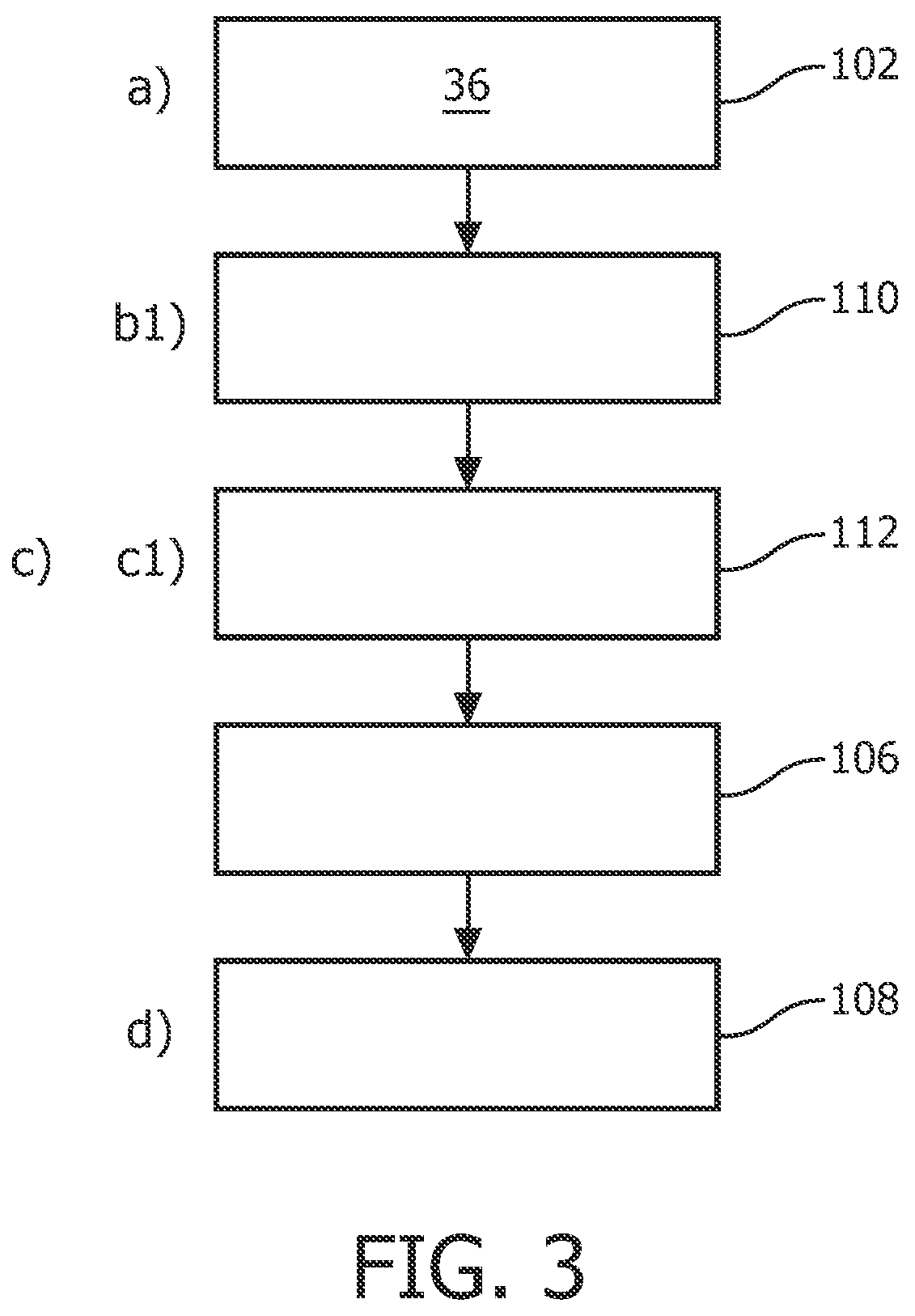
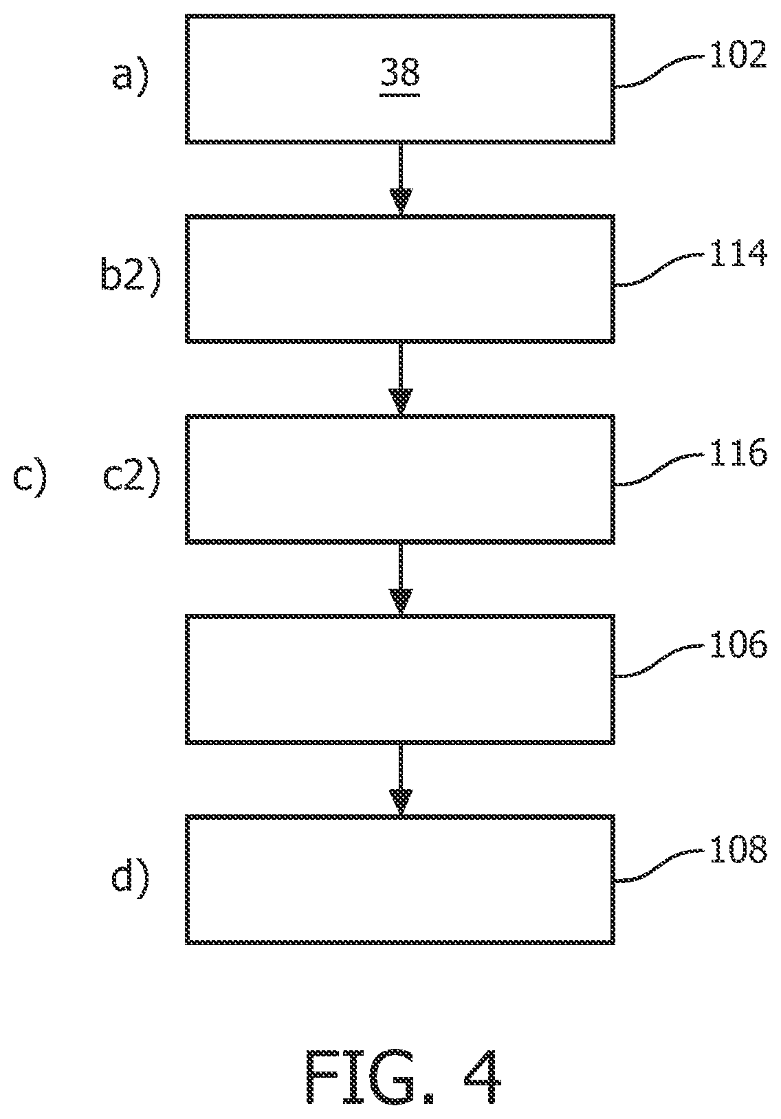
[0043]FIG. 1 shows basic steps of a method 100 for editing a medical 3D surface model, with reference also to FIGS. 2 and 7. The method 100 comprises the following steps:[0044]In a first step 102, also referred to as step a), a 3D surface model 12 of an anatomical structure of an object of interest is provided. The 3D surface model 12 comprises a plurality of surface sub-portions 14. The surface sub-portions 14 each comprise a number of vertices 16. Each vertex 16 is assigned a ranking value.[0045]In a second step 104, also referred to as step b), a point of interest 20 in a visual presentation of the 3D surface model 12 is determined by interaction of a user.[0046]In a third step 106, also referred to as step c), at least one vertex of vertices adjacent to the determined point of interest 20 is identified as an intended vertex 22. The identifying is based on a function of a detected proximity distance 23 to the point of interest 20 and the assigned ranking value.[0047]In a fourth s...


PUM


Abstract

The present invention relates to medical image editing. In order to facilitate the medical image editing process, a medical image editing device (50) is provided that comprises a processor unit (52), an output unit (54), and an interface unit (56). The processor unit (52) is configured to provide a 3D surface model of an anatomical structure of an object of interest. The 3D surface model comprises a plurality of surface sub-portions. The surface sub-portions each comprise a number of vertices, and each vertex is assigned by a ranking value. The processor unit (52) is further configured to identify at least one vertex of vertices adjacent to the determined point of interest as an intended vertex. The identification is based on a function of a detected proximity distance to the point of interest and the assigned ranking value. The output unit (54) is configured to provide a visual presentation of the 3D surface model. The interface unit (56) is configured to determine a point of interest in the visual presentation of the 3D surface model by interaction of a user. The interface unit 56 is further configured to modify the 3D surface model by displacing the intended vertex by manual user interaction. In an example, the output unit (54) is a display configured to display the 3D surface model directly to the user (58).

Description

FIELD OF THE INVENTION[0001]The present invention relates to medical image editing, and in particular to a medical image editing device, to a medical imaging system, to a method of editing a medical 3D surface model, to a computer program element, and to a computer-readable medium.BACKGROUND OF THE INVENTION[0002]Medical image editing, for example, medical image segmentation, is a procedure for dealing with the information provided by medical images. It plays an important role for surgical planning and simulation, radiotherapy planning, and tracking the progress of disease. Computers are used in medical image editing for providing, for example, automated image segmentation. WO 2007 / 034425 A3 relates to a method of adapting a geometric model to image data using multiple partial transformations. However, to ensure accuracy and precision, especially for the medical images with low contrast, noise, and other imaging ambiguities, medical image editing as performed by trained medical pers...

Claims


Application Information

Patent Timeline
Patent Type & Authority Patents(United States)
IPC IPC(8): G06T19/20G06T17/20
CPCG06T19/20G06T17/205G06T2219/2021G06T2210/41G06T2200/24
Inventor WENZEL, FABIANSTEHLE, THOMAS HEIKOMEYER, CARSTENZAGORCHEV, LYUBOMIR GEORGIEVPETERS, JOCHENBERGTHOLDT, MARTIN
Owner KONINKLJIJKE PHILIPS NV
Why Eureka
Try Eureka