Data transmission/reception by frequency hopping

a data transmission and frequency hopping technology, applied in digital transmission, signal allocation, transmission path sub-channel allocation, etc., can solve the problems of low information nitrate, deep fading phenomena affecting the entire radio signal, low cost and complexity, etc., and achieve sufficient independence and preserve the sensitivity of selective frequencies

Active Publication Date: 2020-03-10
ORANGE SA (FR)
View PDF9 Cites 1 Cited by
  • Summary
  • Abstract
  • Description
  • Claims
  • Application Information

AI Technical Summary

Benefits of technology

[0029]Thus, the first transmission frequency is maintained for the synchronization, as for the transmission of useful data, as well as the successive differences in frequency. However, this implementation allows variants. For example, the frequencies of the first set may all be within a narrower frequency band than a frequency band containing the frequencies of the second set. This embodiment for example allows reducing, at the receiver, the complexity of the search for frequencies used for synchronization, in a reduced frequency band. It can typically be narrower than the aforementioned first frequency band.
[0031]Thus, the hop sequence is not specified as a series of channels or frequencies but only as a sequence of frequency changes of more or less N Hz. Thus, the entire sequence is only defined relatively, with respect to the initial transmission. The absolute frequencies at which the transmissions are carried out are not known to the receiver (or even possibly to the transmitter, to reduce its complexity). When the entire sequence has been traveled, then in this embodiment it is reused in a loop as many times as necessary (by communication redundancy). This communication redundancy allows the receiver to identify completely the entire sequence of hops. If it is chosen to first send a synchronization signal before sending useful data, once the entire synchronization signal has been transmitted (transmission of at least one iteration of the hop sequence), the transmitter begins transmitting useful data, using either the same hop sequence or some other sequence defined based on the hop sequence of the synchronization signal.
[0035]Thus, in an advantageous but optional embodiment, it is possible to encode information, for example such as the address of the transmitter, in the actual sequence of frequency hops by changing the value of the frequency hop according to the data symbol to be carried. For example, the differences in frequency defining the frequency hop can characterize the transmitter. In that particular case, knowledge of the transmitter address may allow, for example, using a different sequence of hops specific to the transmitter / receiver pair for the rest of the exchange. For example, the sequence of hops identified during synchronization allows identifying the transmitter and communicating with the transmitter according to another predefined sequence of hops (for example stored in a database where it is linked to some identifier of the transmitter).
[0036]In one embodiment, a receiver, to which data is to be sent, scans the first frequency band to identify the first frequency and a first portion at least of said successive frequencies which, starting at the first frequency, comply with said successive values for the respective differences in frequency. In particular, this first portion at least of the successive frequencies allows the receiver to identify the succession of reception frequencies for useful data to be received from the data transmitter.
[0042]The data are therefore not transmitted on a single channel but rather over all of the band accessible to the system, which provides the benefits of a broadband channel while preserving the sensitivity of selective frequencies. It is preferable to provide a scheme of redundancy and interleaving which is sized to ensure sufficient independence between data transmitted on the same channel.

Problems solved by technology

As the disadvantage is a particularly low information nitrate, this approach is reserved for transmitters of very low cost and complexity which transmit only very small amounts of data.
This choice can result in deep fading phenomena affecting the entire radio signal.
To prevent this phenomenon from significantly altering the radio link, it is important that the operators size the link budget of the radio link to have a significant operating margin, which limits the effective range of these networks accordingly.
However, the use of this technique requires a high level of performance (in terms of stability and speed of oscillators) and a very good quality of synchronization from the radio frequency stages of the terminals, which is both complex electronically and expensive in terms of energy consumption.
These techniques thus remain out of reach for the most limited devices.

Method used


Image

  • Data transmission/reception by frequency hopping
  • Data transmission/reception by frequency hopping
  • Data transmission/reception by frequency hopping

Examples


Embodiment Construction

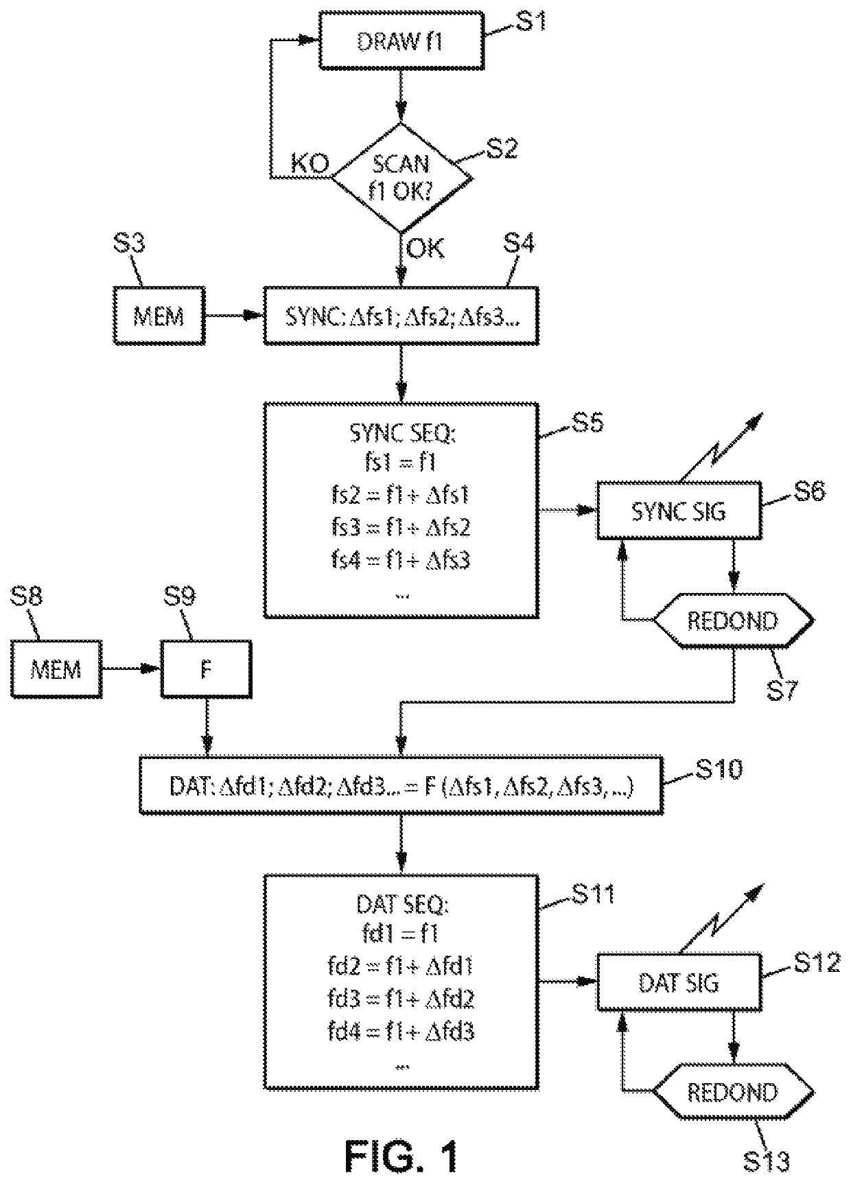
[0054]Referring to FIG. 1 which illustrates the implementation of an exemplary embodiment of the method at a transmitter, in a first step S1, the transmitter randomly selects a frequency f1 within the entire band of available frequencies (said “first frequency band”, for example around 868 MHz for LoRA® or Sigfox®).

[0055]In one particular embodiment, in step S2, the transmitter listens for whether or not the channel corresponding to this frequency f1 is busy, and if this frequency is busy (KO arrow exiting test S2), randomly selects a different other frequency f1, and again checks the availability of the corresponding channel. The transmitter may for example perform this verification step according to the principle of “CSMA” (“Carrier sense multiple access”) or “LBT” (“Listen before talk”). The new frequency tested is different from the initial value, for example by a selected distance (typically greater than the bandwidth of the useful signal). In this manner it is possible to take...


PUM


Abstract

The invention relates to a method for the telecommunication of data by frequency hopping in a first frequency band, wherein the frequency hops follow a predetermined time sequence, known at least to a data transmitter, characterized in that it comprises the following steps implemented by said data transmitter:defining, from a pseudo-random sample, successive values of respective differences in frequency (Δfs1, Δfs2, Δfs3, . . . ; Δfd1, Δfd2, Δfd3, etc.) in order to determine the hopping time sequence starting at a first frequency (f1),transmitting to at least one data receiverat a first frequency (f1), said first frequency being randomly selected (S1) within the first frequency band,then at successive frequencies (S5) which, starting at the first frequency, comply with said successive values of respective differences in frequency, said successive values of differences in frequency defining, at reception, a succession of reception frequencies for useful data to be received from said data transmitter.

Description

FIELD OF THE INVENTION[0001]The present invention relates to the transmission / reception of data by frequency hopping, for example in a radio frequency communication system.BACKGROUND OF THE INVENTION[0002]Very low bitrate and long range radio frequency communication systems are becoming more prevalent. In fact, this long range expresses the capacity of the radio system to sustain greater attenuation than is customary in the radio channel, which requires increased sensitivity of the receiver.[0003]To achieve these high sensitivities, it is usually proposed to reduce the bandwidth of the radio signal as much as possible, the cost being a very low nitrate. The lover the bandwidth, the lower the noise power collected by the receiver, while the energy of the signal concerned remains the same.[0004]As the disadvantage is a particularly low information nitrate, this approach is reserved for transmitters of very low cost and complexity which transmit only very small amounts of data. For exa...

Claims


Application Information

Patent Timeline
Patent Type & Authority Patents(United States)
IPC IPC(8): H04B1/713H04L5/00H04B1/7136
CPCH04L5/0012H04B1/7136H04L5/0053H04B2001/71367
Inventor SCHWOERER, JEAN
Owner ORANGE SA (FR)
Why Eureka
Try Eureka