Recoilless underwater firearm

a firearm and recoil technology, applied in the field of recoil firearms, can solve the problems of reducing the recoil momentum only by 20-30%, reducing the power of ammunition, and turning the swimmer around, so as to increase the efficiency and safety of shooting

Active Publication Date: 2020-03-17
POLOVNEV ANDREY ALBERTOVICH +1
View PDF11 Cites 3 Cited by
  • Summary
  • Abstract
  • Description
  • Claims
  • Application Information

AI Technical Summary

Benefits of technology

[0020]The objective of the given invention is to increase the efficiency and safety of shooting from recoilless firearm at the expense of the guaranteed elimination of recoil acting on the firearm gun carriage.

Problems solved by technology

The need to create such recoilless underwater firearm is stipulated by the fact that existing restrictions for the allowed energy of recoil at a shot for the shooters (swimmers) who are in the water and for small-sized underwater vehicles, does not allow using a high-impulse ammunition in their firearms, which can provide effective shooting at large underwater objects, including, sharks, whales, tunas, etc.
However, this device for underwater firing reduces the recoil momentum only by 20-30% when using a muzzle brake that limits the power of ammunition, which can be used in firearm of swimmers and small-sized underwater vehicles.
The 12.7 mm ammunition with an underwater projectile weight of 60 g, the gunpowder weight of 15.5 g and projectile muzzle velocity of 750 m / s has the recoil momentum of 6.5 kg×s, which can turn the swimmer around when shooting in the water and is not desirable in hand-held underwater firearm.
It is difficult to implement this condition in real firearms due to tolerance for the time of propellant charges ignition, tolerances for the parameters and weight of propellant charges and projectiles.
Besides, it is possible to completely eliminate the recoil, provided that the active and inert projectiles will leave the barrel at the same time, but it is difficult to realize in real firearm because of the tolerances for barrels and projectiles sizes and the tolerances for the projectiles weight.
It should be noted that the hydraulic impact from the stream of propellant gas exhausting from the barrel into the opposite side of the shot does not allow using the known principle of recoilless dynamo-reactive weapon in underwater armament of swimmers and small-sized underwater vehicles.
However, this firearm does not guarantee the complete elimination of recoil during a shot, because the outer surface of the barrel is constantly pressed against the inner surface of the gun carriage by means of a locking screw and does not provide disconnecting of the barrel from the gun carriage before the shot.
That is why the recoil in this firearm is unpredictable and depends on the locking force of the locking screw and on the friction force of the barrel movement in the gun carriage.
In this case, the greatest recoil from overcoming the initial locking force of the locking screw has an effect until the projectile flies out of the barrel; that can divert the firearm from the point of aiming and reduce the accuracy of the shot.
Moreover, this firearm is not provided for the use of unitary ammunition because the electric primer-igniter, the propellant charge and the projectile are united by the barrel, not by the cartridge case; that makes it difficult to load the barrel before the shot and does not guarantee the specified shot parameters, thus reducing the accuracy and efficiency of the shot.
Perhaps the abovementioned unpredictable recoil during the shot and low accuracy of shooting is acceptable for a flying airplane, but for swimmers and small-sized underwater vehicles that are under the water, as in a state of weightlessness, such unpredictable recoil when shooting from recoilless firearms is unsafe, because even a partial recoil of the shot with a high-impulse ammunition can lead to the loss of their orientation in the water, which excludes the possibility of effective shooting.

Method used


Image

  • Recoilless underwater firearm
  • Recoilless underwater firearm

Examples


Embodiment Construction

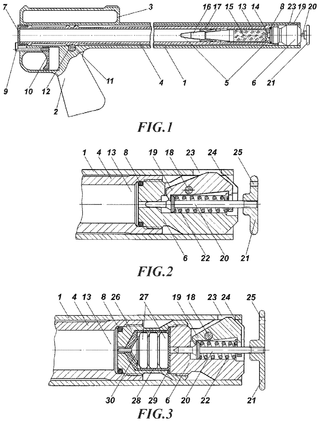
[0043]FIG. 1 shows the longitudinal cross-section of a recoilless underwater hunting firearm of the 12th gauge before a shot. The firearm includes: a gun carriage 1 executed in the form of an open on both sides tube with a pistol grip 2 and a carrying handle 3, which comprises a front sight and a rear sight, a barrel 4 with an ammunition 5, which is closed by a screwing breechblock 6 with a firing mechanism, a sealing plastic cap 7 and a sealing rubber ring 8, which prevents water penetrating into the barrel until a shot.

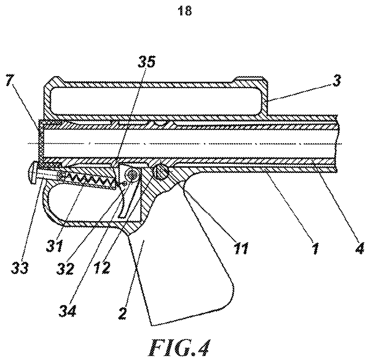
[0044]Fire control tool has a manual drive providing movement of the barrel 4 in the gun carriage 1 for carrying out the shot and contains a trigger bar 9, which is connected with a trigger 10 and with the edge of the muzzle face of the barrel 4, which is closed by a plastic sealing cap 7. The barrel 4 is kept from moving in the gun carriage 1 by a safety-lock 11 with a segmented slot 12, which can be turned around its longitudinal axis by means of an external lever...


PUM


Abstract

The invention relates to recoilless firearms, the gun carriage of which has zero recoil during a shot. The recoilless firearm comprising a gun carriage, a fire control tool, and a barrel, which contains at least a breechblock, a primer-igniter, a propellant charge and a projectile, wherein the barrel is connected to the gun carriage with the possibility of movement in the gun carriage during a shot under the impact of the propellant gas on the breechblock. The barrel is provided with a possibility of disconnecting from the gun carriage before the shot. The fire control tool is connected to the barrel and provides the barrel displacing in the gun carriage for carrying out the shot, and the breechblock is equipped with a firing mechanism, which acts on the primer-igniter when the barrel is displaced in the gun carriage. The invention provides safety of a shot via the guaranteed elimination of recoil during a shot, and also increases the efficacy of neutralizing large targets due to the applicability of high-impulse ammunition when shooting under the water, shooting from the air into the water, shooting in the air and also in weightlessness in the open space.

Description

TECHNICAL FIELD[0001]The invention relates to recoilless firearms, the gun carriage of which has zero recoil during a shot.PRIOR ART[0002]The need to create such recoilless underwater firearm is stipulated by the fact that existing restrictions for the allowed energy of recoil at a shot for the shooters (swimmers) who are in the water and for small-sized underwater vehicles, does not allow using a high-impulse ammunition in their firearms, which can provide effective shooting at large underwater objects, including, sharks, whales, tunas, etc.[0003]The device for underwater firing from a firearm is known (see Description to Patent RU 2498189 C2 of 10 Nov. 2013; the U.S. Pat. No. 8,919,020 B2 of 30 Dec. 2014 and European Patent Specification No 2690390 B1 of 10 Aug. 2016), which allows using any firearm and ammunition of any caliber with an underwater projectile—a cavitating core (see Description to Patents RU 2268455 C1 of 20 Jan. 2006 or RU 2316718 C1 of 10 Feb. 2008; the U.S. Pat. ...

Claims


Application Information

Patent Timeline
Patent Type & Authority Patents(United States)
IPC IPC(8): F41A1/08F41C9/06F42B30/00
CPCF41A1/08F41C9/06F42B30/00
Inventor POLOVNEV, ANDREY ALBERTOVICHPOLOVNEV, LILIYANA BORISOVNA
Owner POLOVNEV ANDREY ALBERTOVICH
Why Eureka
Try Eureka