
Adjusting device for an adjustable rest for a rifle stock

a technology of adjustable rest and adjustable rest, which is applied in the direction of weapons, butts, weapons, etc., can solve the problems of adding to the cost of the adjusting mechanism, adding to the time and cost, and the work required to manufacture or retrofit an existing, so as to reduce time and cost, less susceptible to breakage and exposure to dirt, and more robust

Active Publication Date: 2020-03-17
KALIX TEKNIK
View PDF6 Cites 3 Cited by
  • Summary
  • Abstract
  • Description
  • Claims
  • Application Information

AI Technical Summary

Benefits of technology

[0005]It is an object of the invention to address at least some of the drawbacks, limitations, problems and issues outlined above. It is also an object to provide an adjusting device for an adjustable rest for a rifle stock which reduces time and cost for manufacturing and retrofitting. A further object is to provide an adjusting device for an adjustable rest for a rifle stock which is less susceptible to breakage and exposure to dirt. Another object is to provide an adjusting device for an adjustable rest for a rifle stock which is more ergonomic and visually attractive. A further object is to provide an adjusting device for an adjustable rest for a rifle stock which is more robust and provides reduced play in a release position and during adjustment. A further object is to provide an adjusting device for an adjustable rest for a rifle stock which is more robust and secure and reduces the risk of unwanted release from the rifle stock during a recoil of a rifle.
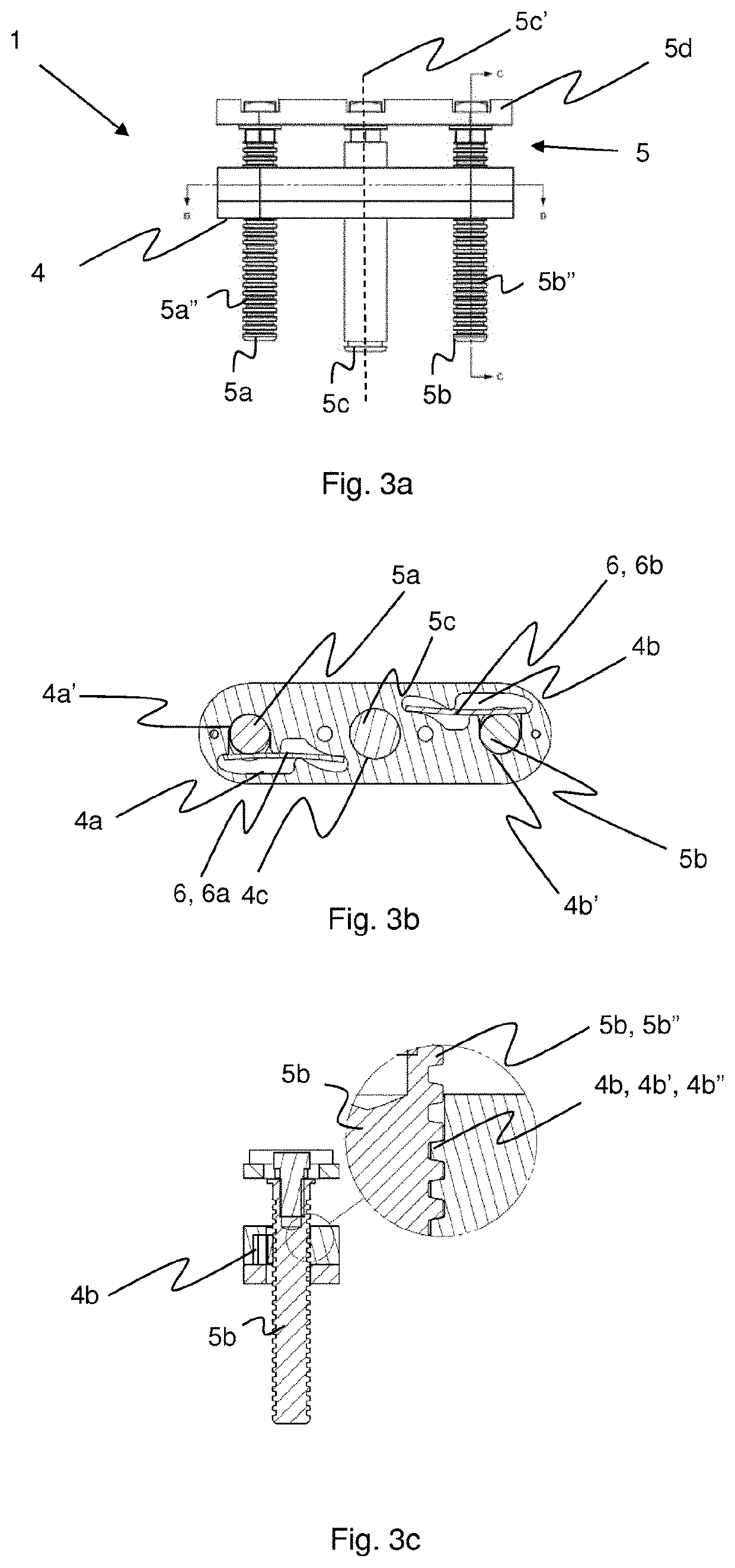
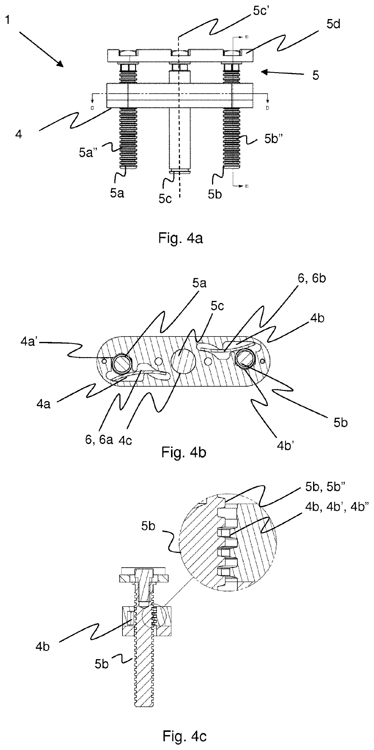
[0022]According to one embodiment, a locking pin is arranged on the pivot shaft to protrude in a perpendicular direction in relation to the pivot axis to prevent removal of the adjusting portion from the first portion.

Problems solved by technology

For instance, a separate adjusting knob is required which adds to the cost of the adjusting mechanism.
Additionally, the work required to manufacture or retrofit an existing rifle including the preparation of a hole adds to the time and cost.
Further a protruding adjusting knob is exposed to the elements and susceptible to wear and physical breakage.
There is a risk that unwanted objects gest entangled in the knob and that dirt enters via the hole in the rifle stock.
The knob further reduces the visible appearance of the rifle stock, as well as it may impair the ergonomics of the rifle stock.

Method used


Image

  • Adjusting device for an adjustable rest for a rifle stock
  • Adjusting device for an adjustable rest for a rifle stock
  • Adjusting device for an adjustable rest for a rifle stock

Examples


Embodiment Construction

[0053]In the following, a detailed description of the invention will be given. In the drawing figures, like reference numerals designate identical or corresponding elements throughout the several figures. It will be appreciated that these figures are for illustration only and are not in any way restricting the scope of the invention.

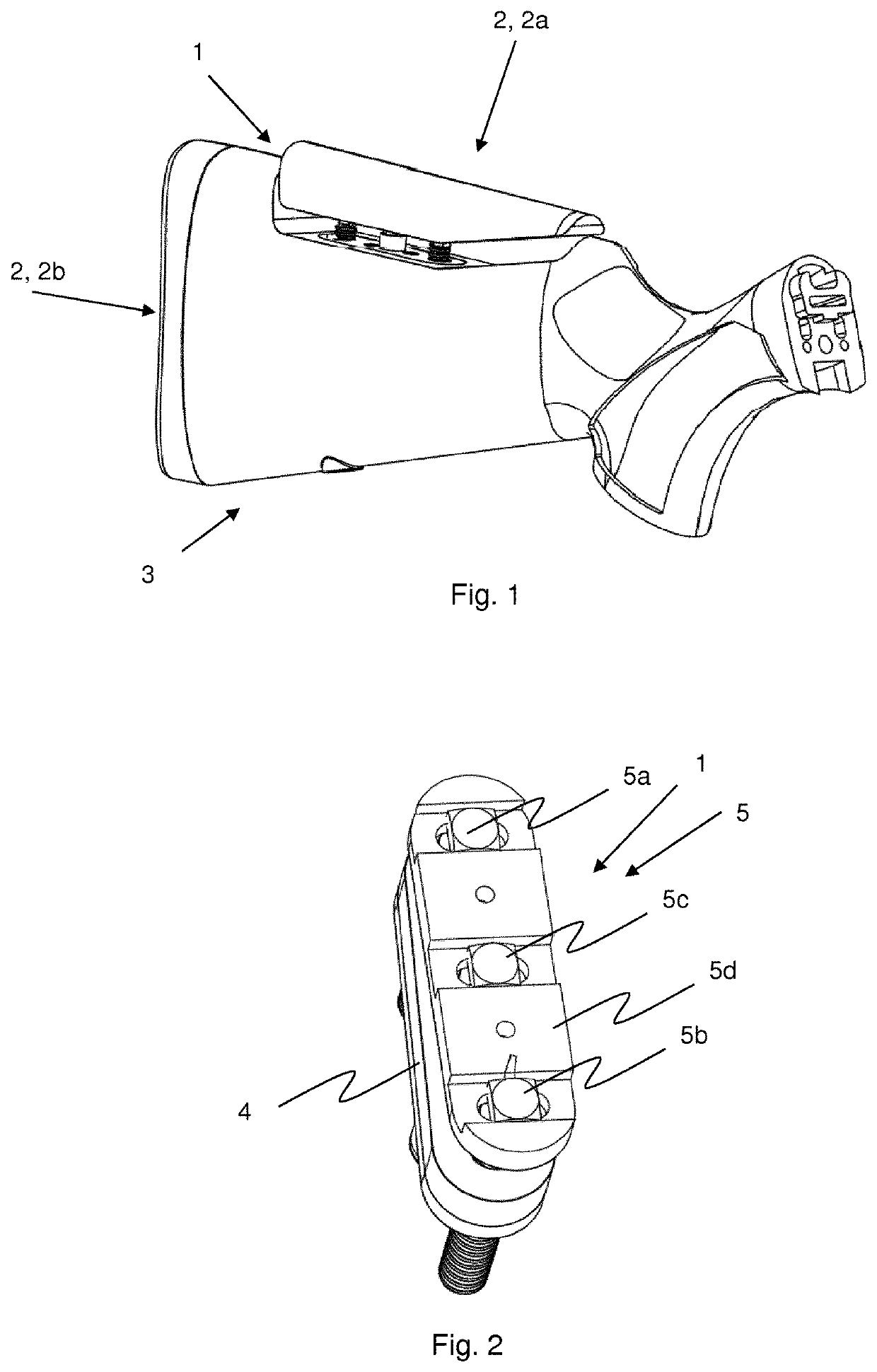
[0054]FIG. 1 illustrates a perspective view of a rifle stock 3 comprising an adjusting device 1 for an adjustable rest 2, 2a, 2b. According to one embodiment, as seen in FIG. 1 the adjusting device 1 is used for adjusting an adjustable cheek rest 2a also known as comb rest. The adjusting of the cheek rest 2a is suitable in order to arrange the cheek and thus head and eyes in a desired relation to a telescopic sight arranged on a rifle. According to one embodiment, the adjusting device 1 is used for adjusting an adjustable shoulder rest 2b which can be seen in FIG. 8b.

[0055]FIG. 2 is a perspective view of an adjusting device 1 according to one embodiment...


PUM


Abstract

Adjusting device (1) for an adjustable rest (2, 2a, 2b) for a rifle stock (3), comprising: a first portion (4) adapted to be fixedly arranged to the rifle stock (3), an adjusting portion (5) adapted to be releasably engaged with the first portion (4) and movable between an engaged, locking position and a disengaged, release position upon actuation of the adjusting portion (5), wherein the adjusting portion (5) is adjustable in relation to the first portion (4) in a release position, and wherein the adjusting portion is locked in relation to the first portion (4) in the locking position, wherein the adjusting portion (5) is adapted to be fixedly arranged to the adjustable rest (2, 2a, 2b).

Description

CROSS-REFERENCE TO RELATED APPLICATION[0001]This application is a 35 U.S.C. § 371 national stage filing of PCT Application No. PCT / EP2017 / 054405 filed on Feb. 24, 2017, entitled “ADJUSTING DEVICE FOR AN ADJUSTABLE REST FOR A RIFLE STOCK,” which claims priority to Swedish Patent Application No. 1650257-7, filed Feb. 26, 2016, each of which are incorporated herein in their entirety by reference.TECHNICAL FIELD[0002]The present invention relates generally to an adjusting device for an adjustable rest for a rifle stock.BACKGROUND ART[0003]It is known to use adjusting mechanisms for cheek rests for rifle stocks that comprises a separate adjusting handle, button or knob for releasing and locking the cheek rest in relation to the rifle stock. Such adjusting knob is arranged on the side of the rifle stock and enters the interior and the locking portion of the cheek rest of the rifle stock via a hole in the side of the rifle stock.[0004]A number of drawbacks exist with the known art. For ins...

Claims


Application Information

Patent Timeline
Patent Type & Authority Patents(United States)
IPC IPC(8): F41C23/14
CPCF41C23/14
Inventor LUNDBÄCK, MAGNUSHENRIKSSON, DAVIDFORSLUND, ANDREAS
Owner KALIX TEKNIK
Learn More